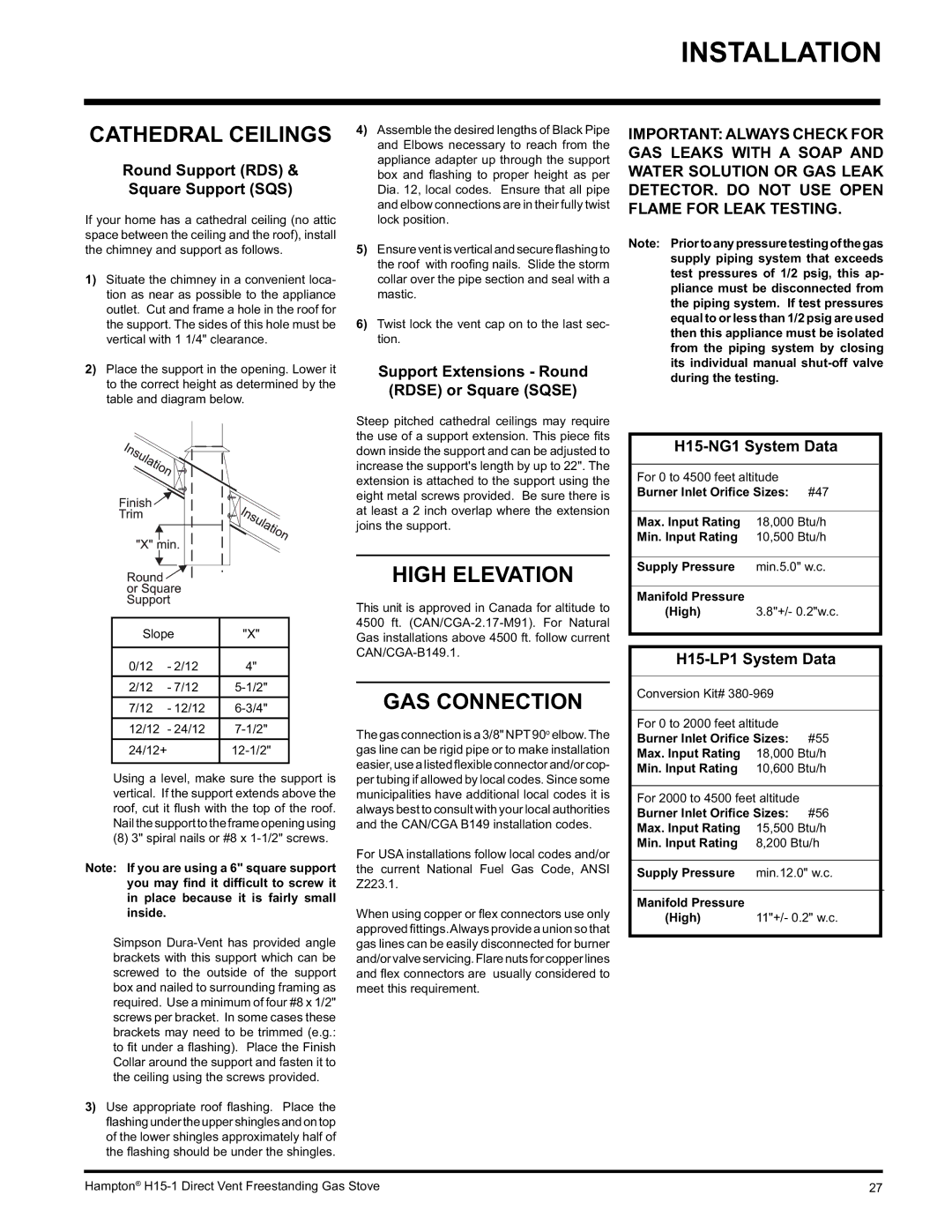
H15-LP1, H15-NG1 specifications
Hampton Direct has established a reputation for producing innovative and high-quality products, and their H15-NG1 and H15-LP1 appliances are no exceptions. These two models have been thoughtfully designed to cater to different needs while sharing several essential features that promise reliability and performance.The H15-NG1 is designed as a natural gas appliance, ideal for users who prefer the efficiency and cost-effectiveness of natural gas heating. Its advanced technology ensures that it operates smoothly and efficiently, providing consistent heating without compromising safety. Users can appreciate the integrated safety features, including automated shut-off mechanisms and flame detection systems. The H15-NG1 also has adjustable heat settings, giving users the flexibility to control the temperature according to their requirements.
On the other hand, the H15-LP1 is specifically designed for propane users. This model is perfect for those who utilize propane as a primary energy source in their households. Similar to its counterpart, the H15-LP1 boasts a powerful heating system that can quickly warm up large spaces, making it an excellent choice for both indoor and outdoor applications. It also includes safety features such as a pressure regulator, ensuring a stable flow of propane that enhances both efficiency and safety.
Both the H15-NG1 and H15-LP1 are constructed with durable materials, ensuring longevity and resilience in various conditions. They are easy to install and user-friendly, making them suitable for users of all experience levels.
Another significant feature of both models is their energy efficiency, which not only provides savings on utility bills but also contributes to an eco-friendly lifestyle. They are equipped with innovative heating technology that maximizes heat output while minimizing energy consumption. This focus on sustainability aligns with contemporary standards for energy-efficient home appliances.
In summary, the Hampton Direct H15-NG1 and H15-LP1 offer impressive features and technologies designed to meet diverse heating needs. With a commitment to safety, efficiency, and user convenience, these models stand out as reliable choices for homeowners looking for effective heating solutions. Whether you prefer natural gas or propane, both units promise a blend of performance, durability, and ease of use.

