INSTALLATION


LOCATING YOUR


OPTIONAL FAN


GAS STOVE


INSTALLATION

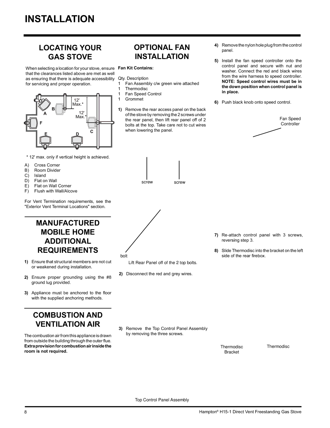
When selecting a location for your stove, ensure

Fan Kit Contains:

that the clearances listed above are met as well

Qty. Description

as ensuring that there is adequate accessibility

for servicing and proper operation.

1

Fan Assembly c/w green wire attached


1

Thermodisc


1

Fan Speed Control


1

Grommet


1)

Remove the rear access panel on the back


of the stove by removing the 2 screws under


the rear panel, then lift rear panel off of 2


bolts at the top. Take care not to cut wires


when lowering the panel.


4)Remove the nylon hole plug from the control panel.

5)Install the fan speed controller onto the control panel and secure with nut and washer. Connect the red and black wires from the wire harness to speed controller.

NOTE: Speed control wires must be in the down position when control panel is in place.

6)Push black knob onto speed control.

Fan Speed

Controller

* 12' max. only if vertical height is achieved.

A)Cross Corner

B)Room Divider

C)Island

D)Flat on Wall

E)Flat on Wall Corner

F)Flush with Wall/Alcove

For Vent Termination requirements, see the "Exterior Vent Terminal Locations" section.

MANUFACTURED

MOBILE HOME

ADDITIONAL

REQUIREMENTS

1)Ensure that structural members are not cut or weakened during installation.

2)Ensure proper grounding using the #8 ground lug provided.

3)Appliance must be anchored to the fl oor with the supplied anchoring methods.

COMBUSTION AND VENTILATION AIR

The combustion air from this appliance is drawn from outside the building through the outer fl ue.

Extra provision for combustion air inside the room is not required.

screw screw

bolt

Lift Rear Panel off of the 2 top bolts.

2)Disconnect the red and grey wires.

3)Remove the Top Control Panel Assembly by removing the three screws.

7)Re-attach control panel with 3 screws, reversing step 3.

8)Slide Thermodisc into the bracket on the left side of the rear fi rebox.

Thermodisc Thermodisc Bracket

Top Control Panel Assembly

8

Hampton® H15-1 Direct Vent Freestanding Gas Stove

Page 8
Image 8
Hampton Direct H15-NG1 Optional FAN, Installation, Manufactured Mobile Home Additional Requirements, Fan Kit Contains

H15-LP1, H15-NG1 specifications

Hampton Direct has established a reputation for producing innovative and high-quality products, and their H15-NG1 and H15-LP1 appliances are no exceptions. These two models have been thoughtfully designed to cater to different needs while sharing several essential features that promise reliability and performance.

The H15-NG1 is designed as a natural gas appliance, ideal for users who prefer the efficiency and cost-effectiveness of natural gas heating. Its advanced technology ensures that it operates smoothly and efficiently, providing consistent heating without compromising safety. Users can appreciate the integrated safety features, including automated shut-off mechanisms and flame detection systems. The H15-NG1 also has adjustable heat settings, giving users the flexibility to control the temperature according to their requirements.

On the other hand, the H15-LP1 is specifically designed for propane users. This model is perfect for those who utilize propane as a primary energy source in their households. Similar to its counterpart, the H15-LP1 boasts a powerful heating system that can quickly warm up large spaces, making it an excellent choice for both indoor and outdoor applications. It also includes safety features such as a pressure regulator, ensuring a stable flow of propane that enhances both efficiency and safety.

Both the H15-NG1 and H15-LP1 are constructed with durable materials, ensuring longevity and resilience in various conditions. They are easy to install and user-friendly, making them suitable for users of all experience levels.

Another significant feature of both models is their energy efficiency, which not only provides savings on utility bills but also contributes to an eco-friendly lifestyle. They are equipped with innovative heating technology that maximizes heat output while minimizing energy consumption. This focus on sustainability aligns with contemporary standards for energy-efficient home appliances.

In summary, the Hampton Direct H15-NG1 and H15-LP1 offer impressive features and technologies designed to meet diverse heating needs. With a commitment to safety, efficiency, and user convenience, these models stand out as reliable choices for homeowners looking for effective heating solutions. Whether you prefer natural gas or propane, both units promise a blend of performance, durability, and ease of use.