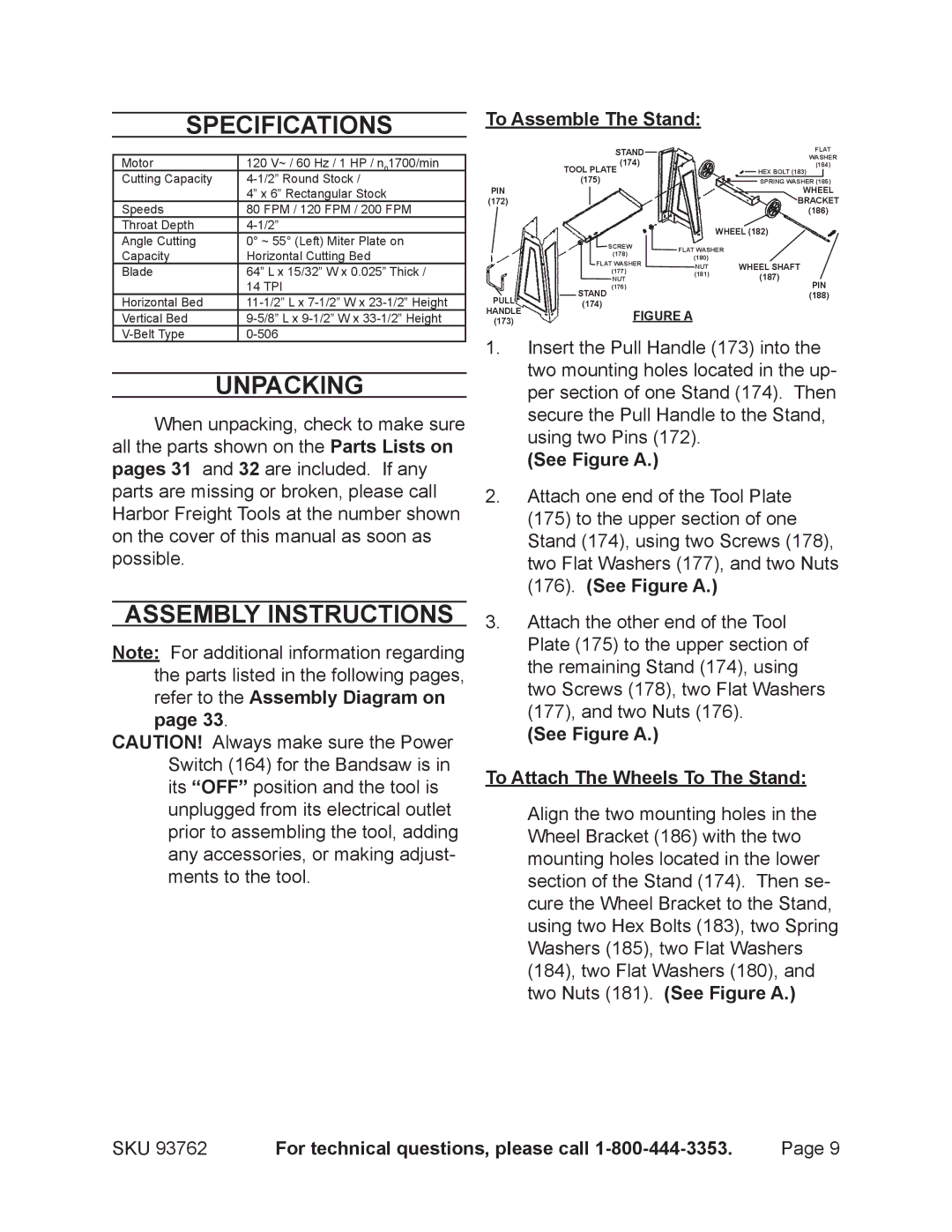
93762 specifications
Harbor Freight Tools is renowned for offering a range of high-quality tools at affordable prices, and the 93762 model is no exception. This product is an essential addition to both professional and DIY enthusiasts' toolkits, designed to enhance efficiency and performance.One of the main features of the Harbor Freight Tools 93762 is its powerful motor. With a robust design, this tool is engineered to deliver optimal performance for a variety of tasks, ensuring that users can tackle even the toughest jobs with ease. The high torque output allows for rapid drilling and fastening, making it ideal for both woodworking and metalworking applications.
Incorporating advanced technology, the Harbor Freight 93762 features a variable speed control that allows users to adjust the speed to suit their specific needs. This versatility is crucial when working with different materials, as it offers precision and control required for delicate tasks, alongside the power needed for more demanding jobs.
Another standout characteristic of the 93762 is its ergonomic design. The handle is contoured for comfort, providing a secure grip that minimizes user fatigue during prolonged use. This thoughtful design enhances overall handling and maneuverability, making it easier to reach tight spaces and work in challenging angles.
The tool also comes equipped with a durable construction. Made from high-quality materials, the Harbor Freight 93762 is designed to withstand the rigors of regular use while maintaining its efficiency over time. This durability ensures that users can rely on the tool for years to come, making it a worthy investment for any toolbox.
Safety features are also a priority with this model. The built-in safety lock and protective casing provide additional security, allowing users to operate the tool with peace of mind. These features help to prevent accidental starts, ensuring a safer working environment.
In summary, the Harbor Freight Tools 93762 is a versatile, powerful, and user-friendly tool that caters to a broad range of applications. Its powerful motor, variable speed control, ergonomic design, and robust construction make it an ideal choice for professionals and DIYers alike. With the right combination of technology and features, this tool stands out as a reliable option for those looking to enhance their workspace efficiency. Whether tackling home improvement projects or professional jobs, the Harbor Freight 93762 delivers performance that users can trust.

