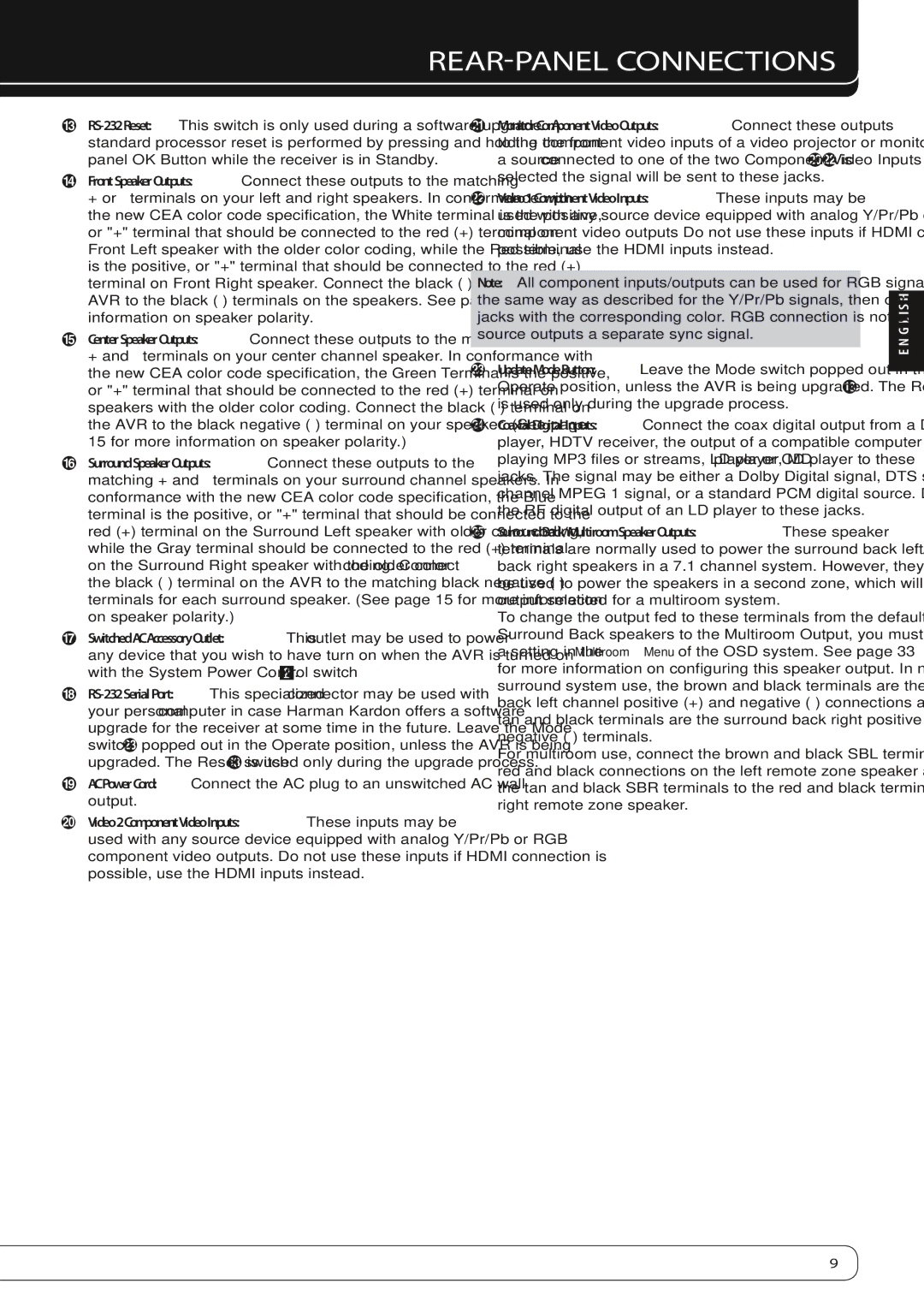
REAR-PANEL CONNECTIONS
C
DFront Speaker Outputs: Connect these outputs to the matching + or – terminals on your left and right speakers. In conformance with the new CEA color code specification, the White terminal is the positive, or "+" terminal that should be connected to the red (+) terminal on Front Left speaker with the older color coding, while the Red terminal is the positive, or "+" terminal that should be connected to the red (+) terminal on Front Right speaker. Connect the black
ECenter Speaker Outputs: Connect these outputs to the matching + and – terminals on your center channel speaker. In conformance with the new CEA color code specification, the Green Terminal is the positive, or "+" terminal that should be connected to the red (+) terminal on speakers with the older color coding. Connect the black
FSurround Speaker Outputs: Connect these outputs to the matching + and – terminals on your surround channel speakers. In conformance with the new CEA color code specification, the Blue terminal is the positive, or "+" terminal that should be connected to the red (+) terminal on the Surround Left speaker with older color coding, while the Gray terminal should be connected to the red (+) terminal
on the Surround Right speaker with the older color coding . Connect the black
GSwitched AC Accessory Outlet: This outlet may be used to power any device that you wish to have turn on when the AVR is turned on with the System Power Control switch 1.
H
your personal computer in case Harman Kardon offers a software upgrade for the receiver at some time in the future. Leave the Mode switch Mpopped out in the Operate position, unless the AVR is being upgraded. The Reset switch Cis used only during the upgrade process.
IAC Power Cord: Connect the AC plug to an unswitched AC wall output.
JVideo 2 Component Video Inputs: These inputs may be used with any source device equipped with analog Y/Pr/Pb or RGB component video outputs. Do not use these inputs if HDMI connection is possible, use the HDMI inputs instead.
KMonitor Component Video Outputs: Connect these outputs to the component video inputs of a video projector or monitor. When
a source connected to one of the two Component Video Inputs JLis selected the signal will be sent to these jacks.
LVideo 1 Component Video Inputs: These inputs may be used with any source device equipped with analog Y/Pr/Pb or RGB component video outputs Do not use these inputs if HDMI connection is possible, use the HDMI inputs instead.
Note: All component inputs/outputs can be used for RGB signals too, in the same way as described for the Y/Pr/Pb signals, then connected to the jacks with the corresponding color. RGB connection is not possible if the source outputs a separate sync signal.
MUpdate Mode Button: Leave the Mode switch popped out in the Operate position, unless the AVR is being upgraded. The Reset switch C is used only during the upgrade process.
NCoaxial Digital Inputs: Connect the coax digital output from a DVD player, HDTV receiver, the output of a compatible computer sound card
playing MP3 files or streams, LD player, MD player or CD player to these jacks. The signal may be either a Dolby Digital signal, DTS signal, a 2 channel MPEG 1 signal, or a standard PCM digital source. Do not connect the RF digital output of an LD player to these jacks.
OSurround Back/Multiroom Speaker Outputs: These speaker terminals are normally used to power the surround back left/surround back right speakers in a 7.1 channel system. However, they may also be used to power the speakers in a second zone, which will receive the output selected for a multiroom system.
To change the output fed to these terminals from the default of the
Surround Back speakers to the Multiroom Output, you must change a setting in the Multiroom Menu of the OSD system. See page 33 for more information on configuring this speaker output. In normal surround system use, the brown and black terminals are the surround back left channel positive (+) and negative
For multiroom use, connect the brown and black SBL terminals to the red and black connections on the left remote zone speaker and connect the tan and black SBR terminals to the red and black terminals on the right remote zone speaker.
ENGLISH
9