North Star
EPA Certified Fireplace
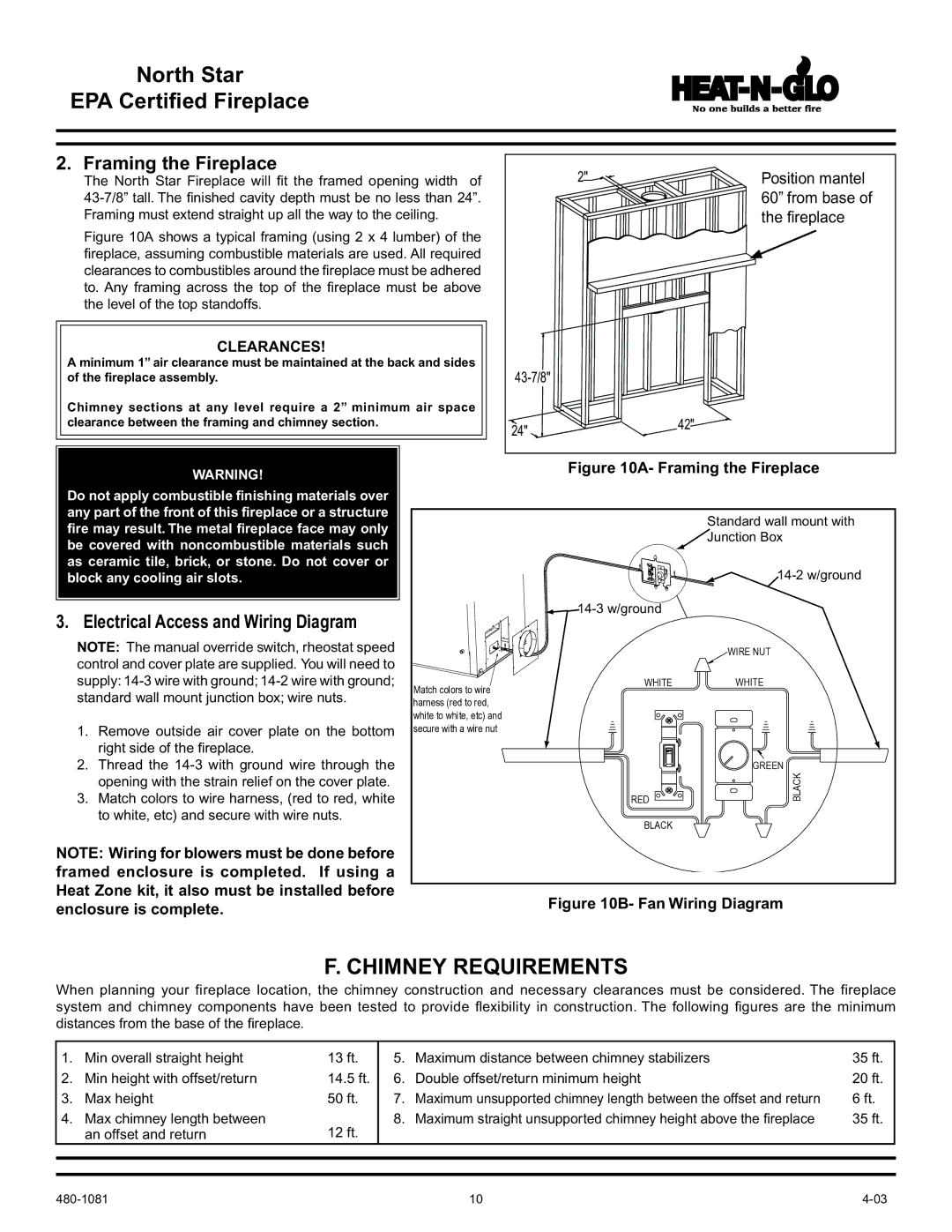
2. Framing the Fireplace
The North Star Fireplace will fit the framed opening width of
Figure 10A shows a typical framing (using 2 x 4 lumber) of the fireplace, assuming combustible materials are used. All required clearances to combustibles around the fireplace must be adhered to. Any framing across the top of the fireplace must be above the level of the top standoffs.
CLEARANCES!
A minimum 1” air clearance must be maintained at the back and sides of the fireplace assembly.
Chimney sections at any level require a 2” minimum air space clearance between the framing and chimney section.
WARNING!
2" | Position mantel |
| 60” from base of |
| the fireplace |
| |
24" | 42" |
|
Figure 10A- Framing the Fireplace
Do not apply combustible finishing materials over any part of the front of this fireplace or a structure fire may result. The metal fireplace face may only be covered with noncombustible materials such as ceramic tile, brick, or stone. Do not cover or block any cooling air slots.
3. Electrical Access and Wiring Diagram
NOTE: The manual override switch, rheostat speed control and cover plate are supplied. You will need to supply:
1.Remove outside air cover plate on the bottom right side of the fireplace.
2.Thread the
3.Match colors to wire harness, (red to red, white to white, etc) and secure with wire nuts.
NOTE: Wiring for blowers must be done before framed enclosure is completed. If using a Heat Zone kit, it also must be installed before enclosure is complete.
Match colors to wire harness (red to red, white to white, etc) and secure with a wire nut
Standard wall mount with
Junction Box
![]()
![]() 14-3
14-3
WIRE NUT
WHITEWHITE
| GREEN |
RED | BLACK |
| |
BLACK |
|
Figure 10B- Fan Wiring Diagram
F. CHIMNEY REQUIREMENTS
When planning your fireplace location, the chimney construction and necessary clearances must be considered. The fireplace system and chimney components have been tested to provide flexibility in construction. The following figures are the minimum distances from the base of the fireplace.
1. | Min overall straight height | 13 ft. | 5. | Maximum distance between chimney stabilizers | 35 ft. |
2. | Min height with offset/return | 14.5 ft. | 6. | Double offset/return minimum height | 20 ft. |
3. | Max height | 50 ft. | 7. | Maximum unsupported chimney length between the offset and return | 6 ft. |
4. | Max chimney length between | 12 ft. | 8. | Maximum straight unsupported chimney height above the fireplace | 35 ft. |
| an offset and return |
|
|
| |
|
|
|
|
|
|
|
|
|
|
|
|
10 |