North Star
EPA Certified Fireplace
17. Alternate materials worksheet
How to determine if alternate floor protection materials are acceptable:
All floor protection must be
PROCEDURE:
1. Convert specification to
|
|
|
| 1 | x T | ||
|
| R = |
| ||||
|
| K x 12 | |||||
1 | x T | ||||||
k | |||||||
|
|
|
|
|
| ||
2.Determine the
i.Use the formula in step (1) to convert values not expressed as “R”.
ii.For multiple layers, add
3.If the overall
EXAMPLE: The specified floor protector should be 3/4 inch thick material with a
|
| 1 |
| = | 1 |
| x 0.75 = 0.893 | |||
Step (a): Use formula above to convert specification to | R = k x T | .84 |
| |||||||
|
|
|
|
| ||||||
Step (b): Calculate R of proposed system. 4" brick of r = 0.2, therefore: | 1/8" mineral board of k = 0.29, therefore: | |||||||||
Rbrick = 0.2 x 4 = 0.431 | Rmineral board | = | 1 | x 0.125 = 0.431 | ||||||
0.29 | ||||||||||
|
|
|
|
|
|
|
|
| ||
Rtotal = Rbrick + Rmineral board = 0.8 + 0.431 = 1.231
Step (c): Compare proposed system Rtotal of 1.231 to specified R of 0.893. Since proposed system Rtotal is greater than required, the system is acceptable.
DEFINITIONS |
| (ft2)(hr)(oF) | k = Btu(in) = K x 12 | K = | Btu(ft) | 2 | o | F)= | 1 | ||||
= | Btu |
| 2 | (hr)(oF) | r = (ft | )(hr)( | k | ||||||
|
| 2 | o | F) |
| ft | (Btu)(in) | ||||||
|
|
|
| ft | (hr)( |
|
|
|
| ||||
18. Position the Hearth Extension |
|
|
|
|
|
|
| ||||||
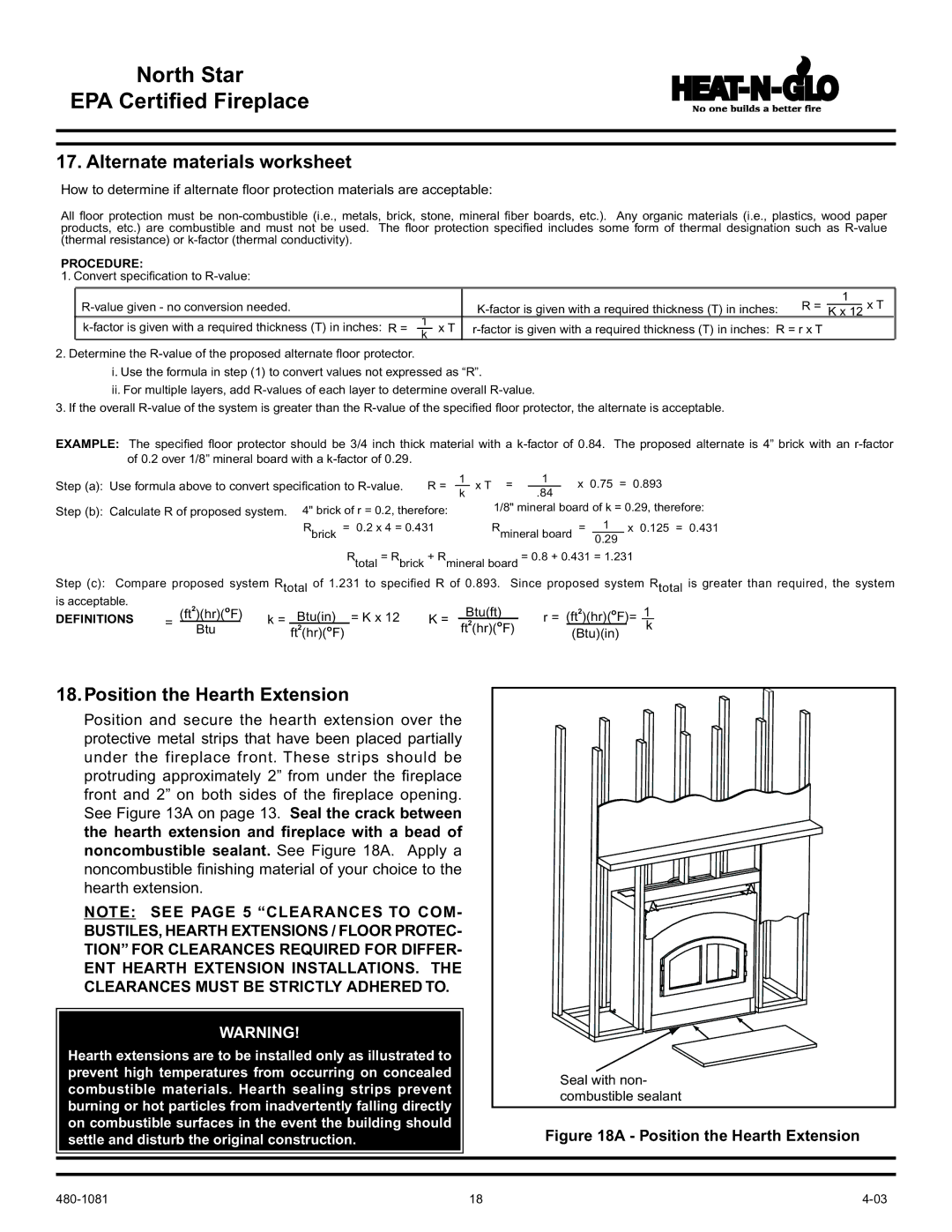
Position and secure the hearth extension over the |
|
|
|
|
| ||||||||
protective metal strips that have been placed partially |
|
|
|
|
| ||||||||
under the fireplace front. These strips should be |
|
|
|
|
| ||||||||
protruding approximately 2” from under the fireplace |
|
|
|
|
| ||||||||
front and 2” on both sides of the fireplace opening. |
|
|
|
|
| ||||||||
See Figure 13A on page 13. Seal the crack between |
|
|
|
|
| ||||||||
the hearth extension and fireplace with a bead of |
|
|
|
|
| ||||||||
noncombustible sealant. See Figure 18A. Apply a |
|
|
|
|
| ||||||||
noncombustible finishing material of your choice to the |
|
|
|
|
| ||||||||
hearth extension. |
|
|
|
|
|
|
|
|
|
|
| ||
NOTE: SEE PAGE 5 “CLEARANCES TO COM- |
|
|
|
|
| ||||||||
BUSTILES, HEARTH EXTENSIONS / FLOOR PROTEC- |
|
|
|
|
| ||||||||
TION” FOR CLEARANCES REQUIRED FOR DIFFER- |
|
|
|
|
| ||||||||
ENT HEARTH EXTENSION INSTALLATIONS. THE |
|
|
|
|
| ||||||||
CLEARANCES MUST BE STRICTLY ADHERED TO. |
|
|
|
|
|
| |||||||
|
|
| WARNING! |
|
|
|
|
|
|
|
|
| |
Hearth extensions are to be installed only as illustrated to |
|
|
|
|
|
| |||||||
prevent high temperatures from occurring on concealed |
|
| Seal with non- | ||||||||||
combustible materials. Hearth sealing strips prevent |
|
| |||||||||||
|
| combustible sealant | |||||||||||
burning or hot particles from inadvertently falling directly |
|
| |||||||||||
|
|
|
|
|
| ||||||||
on combustible surfaces in the event the building should |
|
| Figure 18A - Position the Hearth Extension | ||||||||||
settle and disturb the original construction. |
|
|
| ||||||||||
|
|
|
|
|
|
| 18 |
|
|
| |||
