Manuals
/
Brands
/
Household Appliance
/
Indoor Fireplace
/
Hearth and Home Technologies
/
Household Appliance
/
Indoor Fireplace
Hearth and Home Technologies
- page 28
Models:
CD4236MILR
CD4236MIR
CD4236MLR
CD4236MR
CD4842MILR
CD4842MIR
CD4842MLR
CD4842MR
1
28
76
76
Download
76 pages, 8.38 Mb
Heatilator • Caliber Mesh CD Series-SIT Valve • 4040-849 Rev J • 06/08
28
3. Rear Vent - Horizontal Termination
Figure 7.10
Figure 7.11
No Elbow
One 45° Elbow
18 in. (457 mm) max.
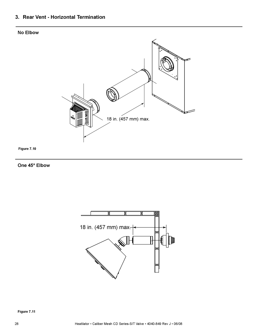
Contents
Main
Owners Manual
CAUTION
Listing Label Information/Location
A. Congratulations
Model #
XXXXXXXXX
Serial # Gas Type
Orifice Size
Safety Alert Key:
Table of Contents
1 Listing and Code Approvals
User Guide
2 Operating Instructions
3 Maintenance and Service
= Contains updated information.
14 Appliance Setup
15 Troubleshooting
16 Reference Materials
B. Limited Lifetime Warranty
Gas Appliance (Fireplace) Limited Lifetime Warranty
1
B. Tempered Glass Speci cations
C. BTU Speci cations
E. Non-Combustible Materials Speci cation
F. Combustible Materials Speci cation
1
A. Appliance Certi cation
G. Requirements for the Commonwealth of Massachusetts
Installation of Carbon Monoxide Detectors
Approved Carbon Monoxide Detectors
Signage
Inspection
2
B. Your Fireplace
A. Gas Fireplace Safety
User Guide
D. Clear Space
C. Fan Kit (optional)
F. Fixed Glass Assembly
E. Decorative Doors and Fronts
G. Remote Controls, Wall Controls and Wall Switches
LIGHTING INSTRUCTIONS
NATURAL GAS
CAUTION:
WARNING:
TO TURN OFF GAS TO APPLIANCE
FOR YOUR SAFETY READ BEFORE LIGHTING
NATURAL GAS
WARNING:
CAUTION:
WARNING:
K. After Fireplace is Lit
L. Frequently Asked Questions
3
Glass Cleaning
3
A. Maintenance Tasks-Homeowner
Doors, Surrounds, Fronts
Remote Control
Venting
B. Maintenance Tasks-Quali ed Service Technician
Logs
Firebox
Gasket Seal and Glass Assembly Inspection
Control Compartment and Firebox Top
4
A. Typical Appliance System
Installer Guide
B. Design and Installation Considerations
D. Inspect Appliance and Components
C. Tools and Supplies Needed
5
Heatilator Caliber Mesh CD Series-SIT Valve 4040-849 Rev J 06/08 17
5
A. Select Appliance Location
Figure 5.1 Appliance Locations
Model # A B C D E F G H I
B. Construct the Appliance Chase
C. Clearances
D. Mantel and Wall Projections
Mantel Legs or Wall Projections
Mantels
6
Termination Caps Same Height
A. Vent Termination Minimum Clearances
6
S min T
7
A. Approved Pipe
C. Use of Elbows
7
B. Vent Table Key
D. Measuring Standards
H
V
E. Vent Diagrams
1. Top Vent - Horizontal Termination
One Elbow
Page
Installed Vertically
2. Top Vent - Vertical Termination
No Elbow
2. Top Vent - Vertical Termination - (continued)
Page
3. Rear Vent - Horizontal Termination - (continued)
H
H1 max. V1 min.
H
V H
V H H
4. Rear Vent - Vertical Termination
One Elbow
4. Rear Vent - Vertical Termination - (continued)
F. Install Vertical Termination Baf e
8
A. Pipe Clearances to Combustibles
8
B. Wall Penetration Framing
C. Install the Ceiling Firestop
D. Install Attic Insulation Shield
Flat Ceiling Installation
Vaulted Ceiling Installation
9
A. Convert from Top Vent to Rear Vent
9
Page
Page
Page
B. Secure and Level the Appliance
10
10
A. Assemble Pipe Sections (DVP Only)
Attach Pipe to the Firebox Assembly
Assemble Pipe Sections
B. Assemble Vent Sections (SLP Only)
Commercial, Multi-family (Multi-level exceeding two stories), or High-Rise Applications
C. Assemble Slip Sections
D. Secure the Vent Sections
E. Disassemble Vent Sections
F. Install Decorative Ceiling Components (SLP only)
G. Install Metal Roof Flashing
H. Assemble and Install Storm Collar
I. Install RF4-8
SLP-FS
Secure with 4 screws no longer than 1/2 in./13 mm
Apply Sealant Top & Partial Sides
Shingles Trimmed Shingles over Flashing
J. Install Vertical Termination Cap
Storm Collar
Screws
Caulk
Termination Cap
M. Install Horizontal Termination Cap
11
A. Fuel Conversion
B. Gas Pressure
C. Gas Connection
11
12
B. Standing Pilot Ignition System Wiring
A. Wiring Requirements
C. Intelli re Ignition System Wiring
D. Optional Accessories Requirements
E. Electrical Service and Repair
G. Wall Switch Installation for Fan (Optional)
F. Junction Box Installation
13
13
A. Mantel and Wall Projections
Mantels
Combustible
14
I. Place the Rockwool
14
H. Place the Vermiculite
G. Place the Lava Rock
J. Install the Log Assembly
K. Fixed Glass Assembly
Removing Fixed Glass Assembly
Replacing Fixed Glass Assembly
L. Install Trim
Bottom Latch Cover (Lower Floor Cover underneath)
Top Latch Cover
Hood
Firescreen Firescreen Rod
N. Air Shutter Setting
Install Bottom Latch Cover
Install Firescreen Assembly
15
A. Standing Pilot Ignition System
15
A. Standing Pilot Ignition System (continued)
B. Intelli re Ignition System
B. Intelli re Ignition System (continued)
16
16
A. Appliance Dimension Diagram
Model # A B C
B. Vent Components Diagrams
Assembled Height: 24 in./610 mm Diameter: 10 in./254 mm DVP-AS2
26 in. (660 mm)
Page
Page
Fillers
Page
SL-2DVP Adapter
13 in. (330 mm) 15 in. (381 mm)
8-1/8 in. (206 mm)
SLP-HRC-SS
C. Service Parts
CD4236M Series
#22 Log/Grate Assembly
CD4842M Series
#22 Log/Grate Assembly
CD4236M Series
# Description of Part Comments CD4236MRCD4236MLR CD4236MIR CD4236MILR Qty.
IPI Valve Assembly
Standing Pilot Valve Assembly
CD4842M Series
Standing Pilot Valve Assembly
IPI Valve Assembly
D. Optional Components
D. Optional Components (continued)
CD4842M 47 in. Caliber Top-Rear Direct Vent Cir- culating Gas Appliance
CD4236M 41 in. Caliber Top/Rear Direct Vent Cir- culating Gas Appliance
Model # Description
Model # Description
NOTICE