B. Installing Vent Components
After determining which set of starting collars will be used (top or rear), follow venting instructions accordingly.
Venting Out the Rear Vent
Remove the installed rear seal cap from the rear starting collars by cutting the strap at each end. (see Figure 18). Follow the vent configuration tables accordingly.
Remove the insulation from the REAR five inch flue, pull the heat shield out from outside of the firebox.
!WARNING: THE TOP HEAT SHIELD (INSIDE THE FIREBOX) MUST REMAIN ATTACHED IF THE VENT SYSTEM IS ATTACHED TO THE REAR STARTING COLLARS. SEE FIGURE 18.
Venting Out the Top Vent
Remove the two screws in the top vent collar seal cap and remove the top vent collar seal cap and two pieces of in- sulation inside the top two starting collars (See Figure 18).
Remove the heat shield from inside the TOP five inch flue from outside of the firebox.
The glass must be taken off again for positioning the logs when the unit is finally installed in place and finished around it.
!WARNING: THE REAR VENT COLLAR SEAL CAP MUST REMAIN ATTACHED TO THE REAR
VENT COLLARS IF THE VENT SYSTEM ISATTACHED TO THE TOP STARTING COLLARS.
WARNING: FAILURE TO REMOVE INSULATION
!IN THE SET OF COLLARS YOU ARE USING COULD NEGATIVELY AFFECT FIREPLACE PERFORMANCE.
!WARNING: YOU MUST LEAVE THE INSULA- TION IN PLACE IN THE SET OF COLLARS YOU ARE NOT USING. FAILURE TO DO THIS COULD CAUSE A FIRE.
Venting Out Rear | Venting Out Top | |
SEAL | SEAL |
|
CAP | CAP |
|
HEAT | INSULATION |
|
SHIELD |
| |
| DISCARD BOTH | |
| PIECES and |
|
| HEAT SHIELD | HEAT |
DISCARD |
| SHIELD |
INSULATION |
|
|
and |
|
|
HEAT SHIELD |
|
|
|
| CUT |
|
| HERE |
Cut the seal cap |
|
|
strap and remove white |
|
|
gasket material. |
|
|
Figure 18 |
|
|
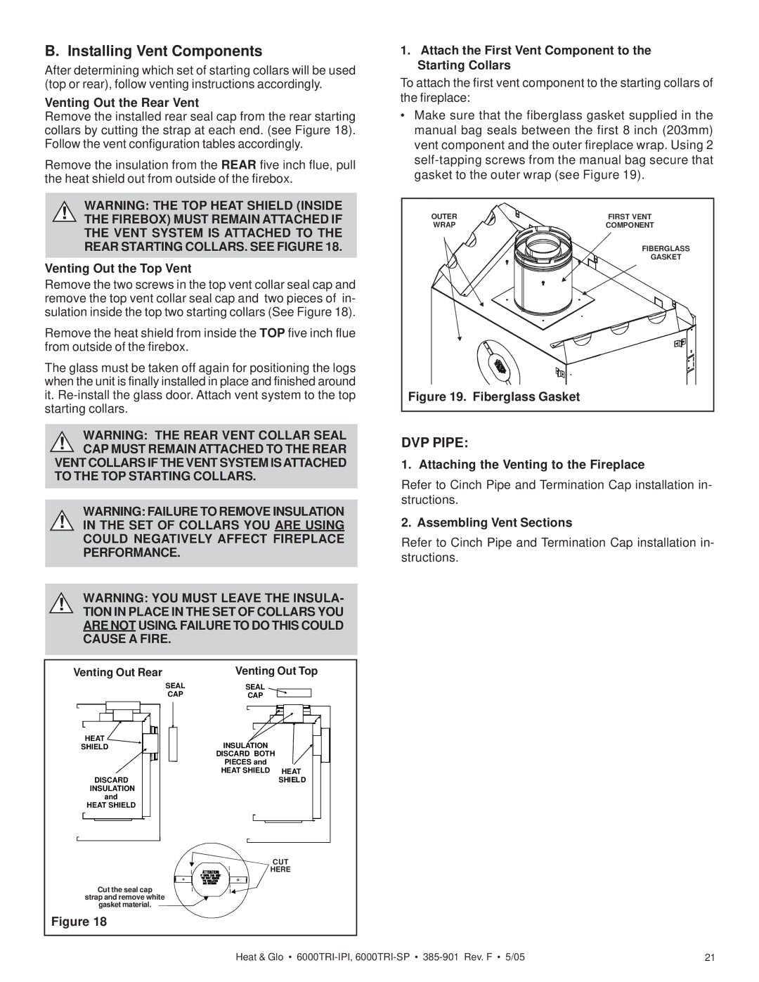
1.Attach the First Vent Component to the Starting Collars
To attach the first vent component to the starting collars of the fireplace:
•Make sure that the fiberglass gasket supplied in the manual bag seals between the first 8 inch (203mm) vent component and the outer fireplace wrap. Using 2
OUTER | FIRST VENT |
WRAP | COMPONENT |
| FIBERGLASS |
| GASKET |
Figure 19. Fiberglass Gasket |
|
DVP PIPE:
1. Attaching the Venting to the Fireplace
Refer to Cinch Pipe and Termination Cap installation in- structions.
2. Assembling Vent Sections
Refer to Cinch Pipe and Termination Cap installation in- structions.
Heat & Glo • | 21 |