If the area above the ceiling is NOT an attic, position and secure the ceiling firestop on the ceiling side of the previously cut and framed hole.
NOTE: There must be NO INSULATION or other combustibles inside the framed firestop opening.
JOIST |
CEILING |
NAILS (4 REQUIRED) |
CEILING FIRESTOP |
Figure 26. Ceiling Firestop (Ceiling Side) |
If the area above the ceiling IS an attic, position and secure the firestop on top of the previously framed hole.
NOTE: Keep insulation away from the vent pipe at least 1 inch (25mm).
| NAILS (4 REQUIRED) |
| RAFTER |
CEILING |
|
| CEILING FIRESTOP |
Figure 27. | Attic Firestop |
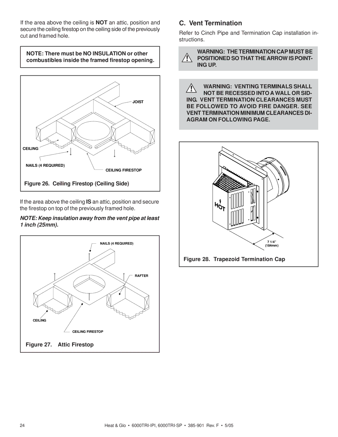
C. Vent Termination
Refer to Cinch Pipe and Termination Cap installation in- structions.
WARNING: THE TERMINATION CAP MUST BE
!POSITIONED SO THAT THE ARROW IS POINT- ING UP.
!WARNING: VENTING TERMINALS SHALL NOT BE RECESSED INTO A WALL OR SID-
ING. VENT TERMINATION CLEARANCES MUST BE FOLLOWED TO AVOID FIRE DANGER. SEE VENT TERMINATION MINIMUM CLEARANCES DI- AGRAM ON FOLLOWING PAGE.
7 1/4” (184mm)
Figure 28. Trapezoid Termination Cap
24 | Heat & Glo • |