Step 4. Positioning, Leveling, and Securing the Fireplace
The diagram below shows how to properly position, level, and secure the fireplace.
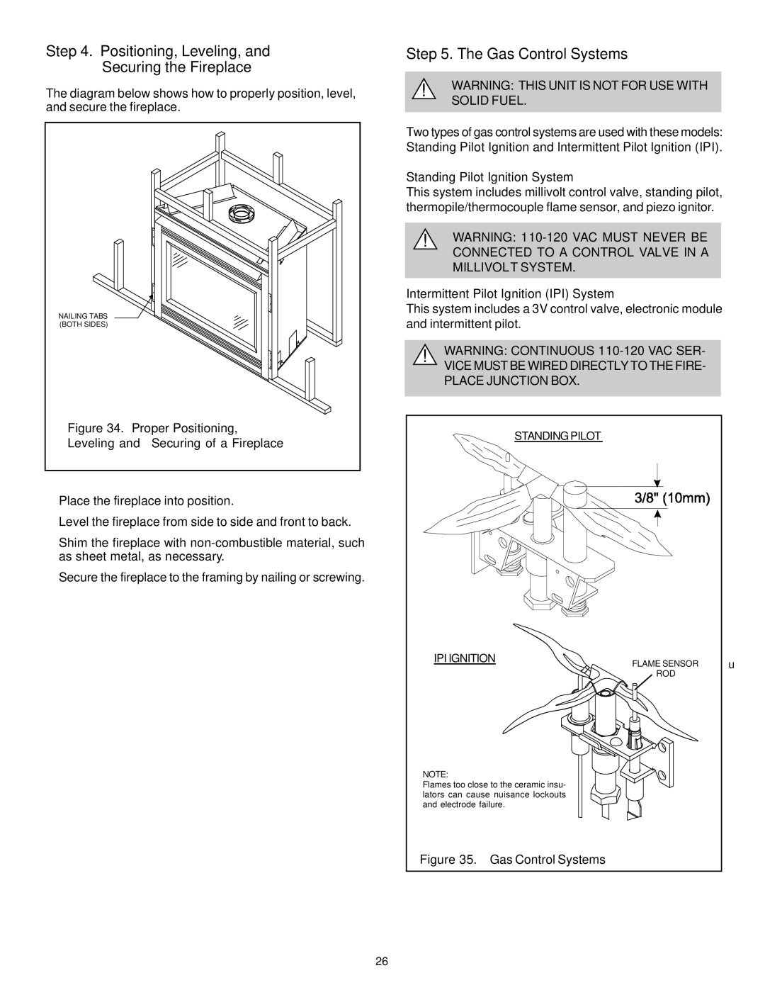
NAILING TABS (BOTH SIDES)
Figure 34. Proper Positioning,
Leveling and Securing of a Fireplace
•Place the fireplace into position.
•Level the fireplace from side to side and front to back.
•Shim the fireplace with
•Secure the fireplace to the framing by nailing or screwing.
Step 5. The Gas Control Systems
!WARNING: THIS UNIT IS NOT FOR USE WITH SOLID FUEL.
Two types of gas control systems are used with these models: Standing Pilot Ignition and Intermittent Pilot Ignition (IPI).
Standing Pilot Ignition System
This system includes millivolt control valve, standing pilot, thermopile/thermocouple flame sensor, and piezo ignitor.
!WARNING:
Intermittent Pilot Ignition (IPI) System
This system includes a 3V control valve, electronic module and intermittent pilot.
!WARNING: CONTINUOUS
VICE MUST BE WIRED DIRECTLY TO THE FIRE- PLACE JUNCTION BOX.
STANDING PILOT
IPI IGNITION | FLAME SENSOR | u |
| ROD |
|
NOTE:
Flames too close to the ceramic insu- lators can cause nuisance lockouts and electrode failure.
Figure 35. Gas Control Systems
26