AT-GRAND-D specifications
The Heat & Glo LifeStyle AT-GRAND-D is an impressive gas fireplace that combines advanced technology with contemporary design. This innovative product caters to homeowners seeking both aesthetic appeal and functional warmth, making it suitable for a variety of living spaces.One of the standout features of the AT-GRAND-D is its expansive viewing area, providing an unobstructed view of the flames. The large glass front enhances the ambiance of any room while maximizing the visual impact of the fire. The fireplace is designed to fit seamlessly into modern and traditional decor, thanks to its diverse finishing options and customizable installation features.
The AT-GRAND-D incorporates advanced technology to enhance efficiency and comfort. One notable technology is the IntelliFire™ ignition system, which offers reliable and easy start-ups. This system ensures that the fireplace ignites quickly at the push of a button, eliminating the hassle of manual lighting. Additionally, it features an optional remote control that allows users to adjust the flame height and heat output, providing the ultimate convenience.
Safety is also a priority in the design of the AT-GRAND-D. It includes a safety screen that prevents accidental contact with the glass, ensuring peace of mind for families with children and pets. The unit is equipped with a temperature sensor, allowing it to automatically adjust the flame to maintain a comfortable environment and prevent overheating.
Another key characteristic of the Heat & Glo LifeStyle AT-GRAND-D is its impressive heat output. With a powerful BTU range, it is capable of effectively heating large areas, making it an excellent heating solution for open-concept living spaces or cozy nooks. Additionally, the fireplace is designed for energy efficiency, providing warmth while minimizing energy consumption.
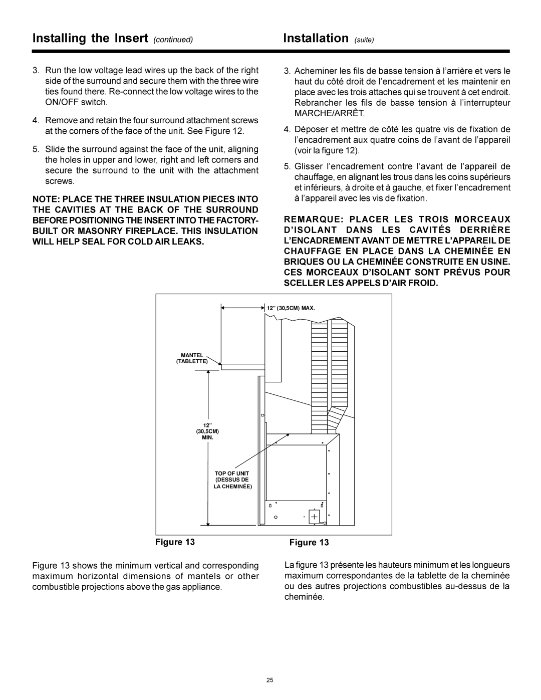
The AT-GRAND-D offers customizable installation options, including the ability to use it as a built-in unit or as a standalone model with a sleek surround. This adaptability allows homeowners to create a unique focal point in their home that suits their specific needs and style preferences.
In summary, the Heat & Glo LifeStyle AT-GRAND-D gas fireplace is a top-tier option for those looking to enhance their living space with warmth and elegance. Its combination of cutting-edge technology, safety features, and stylish design makes it an excellent choice for any modern home.

