Disassembly
6. ROTARY SWITCH
 MODEL : ROTARY SWITCH TYPE MODEL
1. Remove the control box.
2. Open the control box.
3. Remove the 2 screws which fasten the rotary switch.
4. Disconnect all the leads of the rotary switch terminals.
5. Remove the rotary switch. |
|
6. | above |
removal procedure. (See Figure 29) |
|
7. POWER CORD | Figure 29 |
1.Remove the control box.
2.Open the control box.
3.Disconnect the grounding screw from the control box.
4.Disconnect the 2 receptacles.
5.Remove a screw which fastens the clip cord.
(See Figure 30)
6. Remove the power cord. |
|
7. |
|
removal procedure, above. |
|
(Use only one |
|
connection.) |
|
8. If the supply cord of this appliance is damaged, it | Figure 30 |
must be replaced by the special cord. (The |
|
special cord means the cord which has the same |
|
specification marked on the supply cord attached at |
|
the unit.) |
|
Refrigerating Cycle
CAUTION: Discharge the refrigerant system using a FreonTM Recovery System. If there is no valve to attach the recovery system, install one (such as a WATCO
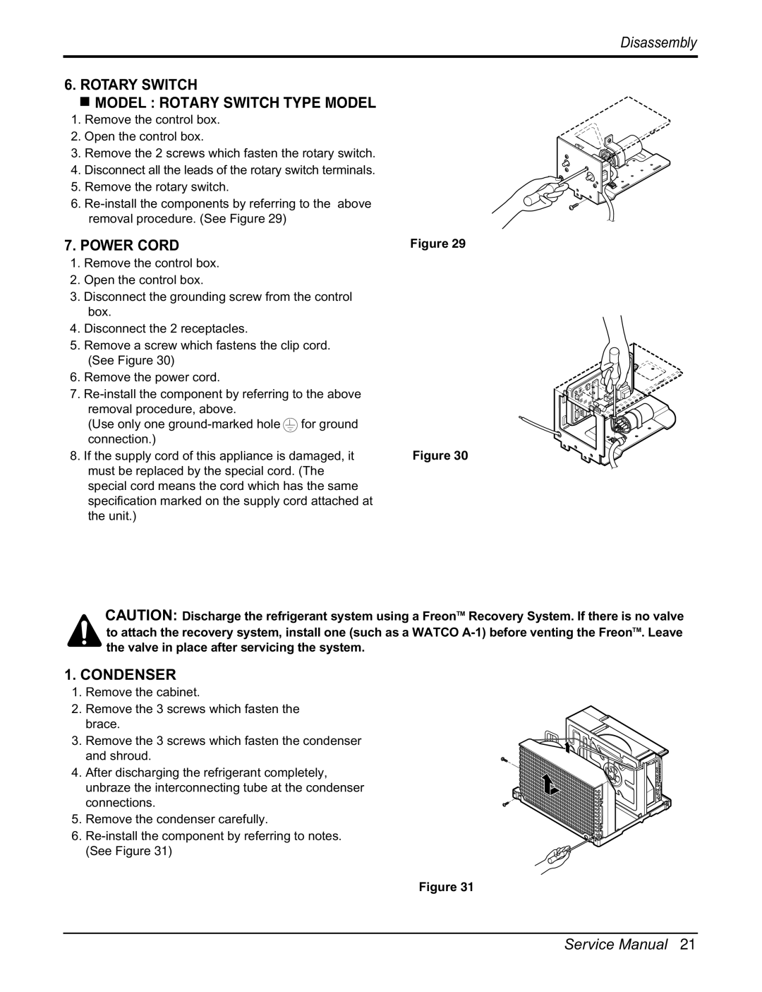
1.CONDENSER
1.Remove the cabinet.
2.Remove the 3 screws which fasten the
brace.
3. Remove the 3 screws which fasten the condenser and shroud.
4. After discharging the refrigerant completely, unbraze the interconnecting tube at the condenser connections.
5. Remove the condenser carefully.
6.
Figure 31
Service Manual 21