INSTALLATION

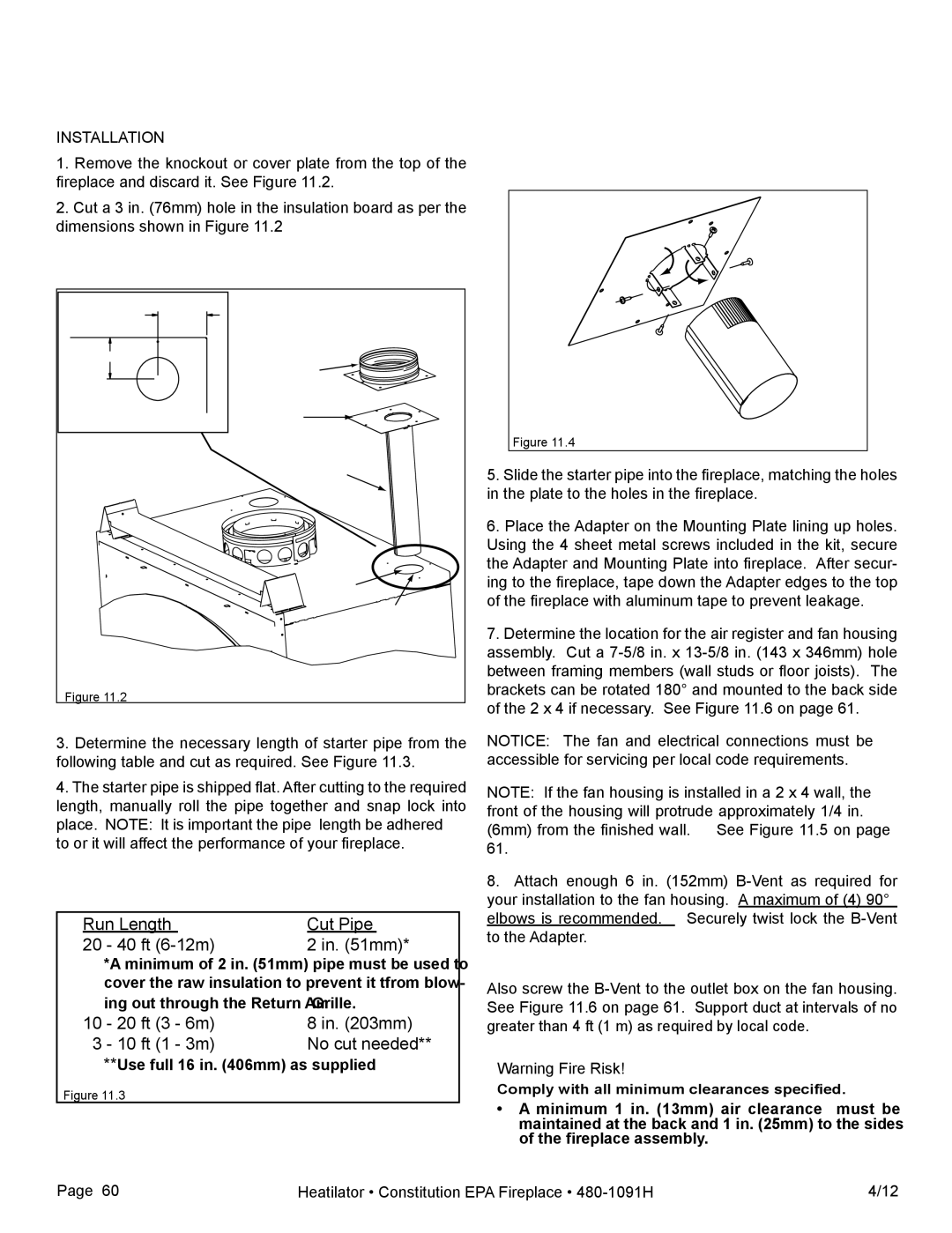
1.Remove the knockout or cover plate from the top of the fireplace and discard it. See Figure 11.2.

2.Cut a 3 in. (76mm) hole in the insulation board as per the dimensions shown in Figure 11.2


3-13/16 in.


(97mm)


3-1/8 in. (79mm)

Adapter


C


L


Mounting


Plate


Starter Pipe


Knockout


hole


.(76mm)


Cuta

3in

board


ininsulation


Figure 11.2


3.Determine the necessary length of starter pipe from the following table and cut as required. See Figure 11.3.

4.The starter pipe is shipped flat. After cutting to the required length, manually roll the pipe together and snap lock into place. NOTE: It is important the pipe length be adhered to or it will affect the performance of your fireplace.

Run Length

Cut Pipe

20

- 40 ft (6-12m)

2 in. (51mm)*


*A minimum of 2 in. (51mm) pipe must be used to


cover the raw insulation to prevent it tfrom blow-


ing out through the Return Air Grille.

10

- 20 ft (3 - 6m)

8 in. (203mm)

3

- 10 ft (1 - 3m)

No cut needed**

**Use full 16 in. (406mm) as supplied

Figure 11.3

Figure 11.4

5.Slide the starter pipe into the fireplace, matching the holes in the plate to the holes in the fireplace.

6.Place the Adapter on the Mounting Plate lining up holes. Using the 4 sheet metal screws included in the kit, secure the Adapter and Mounting Plate into fireplace. After secur- ing to the fireplace, tape down the Adapter edges to the top of the fireplace with aluminum tape to prevent leakage.

7.Determine the location for the air register and fan housing assembly. Cut a 7-5/8 in. x 13-5/8 in. (143 x 346mm) hole between framing members (wall studs or floor joists). The brackets can be rotated 180° and mounted to the back side of the 2 x 4 if necessary. See Figure 11.6 on page 61.

NOTICE: The fan and electrical connections must be accessible for servicing per local code requirements.

NOTE: If the fan housing is installed in a 2 x 4 wall, the front of the housing will protrude approximately 1/4 in. (6mm) from the finished wall. See Figure 11.5 on page 61.

8.Attach enough 6 in. (152mm) B-Vent as required for your installation to the fan housing. A maximum of (4) 90° elbows is recommended. Securely twist lock the B-Vent to the Adapter.

Also screw the B-Vent to the outlet box on the fan housing. See Figure 11.6 on page 61. Support duct at intervals of no greater than 4 ft (1 m) as required by local code.

Warning Fire Risk!

Comply with all minimum clearances specified.

A minimum 1 in. (13mm) air clearance must be maintained at the back and 1 in. (25mm) to the sides of the fireplace assembly.

Page 60

Heatilator • Constitution EPA Fireplace • 480-1091H

4/12

Page 60
Image 60
Heatiator C40 owner manual Run Length Cut Pipe 40 ft 6-12m

C40 specifications

The Heatiator C40 is an innovative heating solution designed to optimize comfort and energy efficiency in residential and commercial spaces. This advanced heating unit combines modern technology with user-friendly features, making it an excellent choice for anyone looking to improve their heating systems.

One of the standout features of the Heatiator C40 is its powerful heating capacity. With an output of up to 40,000 BTUs, this unit is capable of efficiently warming large areas, ensuring that no space is left cold. The C40 utilizes high-efficiency burners that maximize heat output while minimizing fuel consumption. This not only translates to lower energy bills for the consumer but also contributes to a reduced carbon footprint.

The Heatiator C40 is equipped with advanced smart technology, allowing users to control their heating environment remotely. With the Heatiator mobile app, users can adjust the temperature settings, set schedules, and monitor energy usage from their smartphones. This level of control ensures that comfort is maintained without unnecessary energy waste.

Another notable characteristic of the C40 is its versatile design. The unit can be easily installed in various configurations, including wall-mounted, freestanding, or built-in options, making it suitable for any room layout or decor. Its sleek, compact design also ensures that it blends seamlessly into any environment, providing users with both functionality and aesthetic appeal.

Safety is a priority in the design of the Heatiator C40. The unit is equipped with multiple safety features, including overheat protection, a flame failure device, and an automatic shut-off system. These safety measures provide peace of mind, allowing users to enjoy their heating without worry.

Furthermore, the Heatiator C40 operates quietly, making it an ideal choice for bedrooms and living areas where noise can be a distraction. The noise-reduction technology incorporated into the unit ensures that the heating process is unobtrusive, allowing for a peaceful environment.

In summary, the Heatiator C40 is a cutting-edge heating solution that stands out due to its powerful performance, energy efficiency, and user-friendly technology. With its stylish design, safety features, and advanced controls, the C40 is an excellent investment for anyone looking to enhance their heating system while enjoying the comfort of a warm, inviting space. Whether for homes or businesses, the Heatiator C40 promises reliable performance and satisfaction.