KFR-3208GW specifications
Hisense Group, a key player in the global consumer electronics market, has made significant advancements in air conditioning technology with its model KFR-3208GW. Designed to meet the demands of both comfort and energy efficiency, this air conditioning unit stands out for its impressive blend of features and modern technologies.One of the main features of the KFR-3208GW is its powerful cooling capability. With a cooling capacity of 3.2 kW, this unit can quickly lower indoor temperatures, making it ideal for residential and small commercial settings. The inverter technology integrated into the KFR-3208GW allows for precise temperature control while ensuring lower energy consumption, leading to substantial cost savings on electricity bills. This technology enables the compressor to adjust its speed according to the room temperature, thus maintaining a consistent climate without unnecessary energy spikes.
Another highlight of this air conditioning system is its Quiet Operation mode. The KFR-3208GW is designed to operate at low noise levels, making it suitable for bedrooms and other quiet environments. This is especially important for users who prefer a peaceful atmosphere for sleeping or working.
The air conditioning unit also features a multi-functional remote control, allowing users to effortlessly switch between the various modes such as cooling, heating, and dehumidification. The unit is equipped with a precise temperature sensor that ensures optimal performance and enhances user comfort.
Moreover, the KFR-3208GW is designed with advanced filtration systems that improve indoor air quality. The built-in filters are capable of capturing dust, allergens, and other airborne particles, contributing to a healthier living environment. This feature is particularly beneficial for individuals with respiratory issues or allergies.
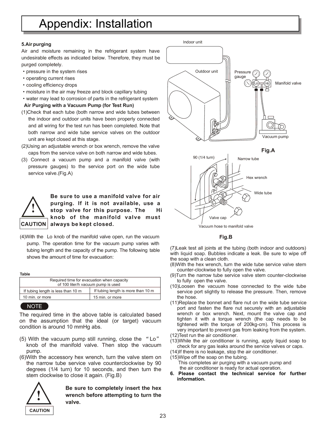
In terms of installation, the KFR-3208GW offers flexibility, catering to different room layouts. Its compact design allows for easy wall mounting, making it an attractive option for space-constrained areas.
Overall, the Hisense Group KFR-3208GW air conditioning unit combines energy efficiency, cutting-edge technology, and user-friendly features, making it a desirable choice for those looking to enhance their indoor comfort while promoting a healthier atmosphere. As consumers continue to seek reliable and efficient cooling solutions, the KFR-3208GW is well positioned to meet these evolving needs.

