Connecting to Video Equipment
(such as a Laser Disc player, a DVD player, a DSS,or a Video Camera)
■ Read SAFETY GUIDELINES ( I to VII ) carefully to ensure maximum safety before proceeding to these steps:
1)Choose an appropriate site and install the product on a level table where the stand is secure.
•Install the monitor to have ready access to a power socket available.
2)Make sure that the video equipment’s power switch is off.
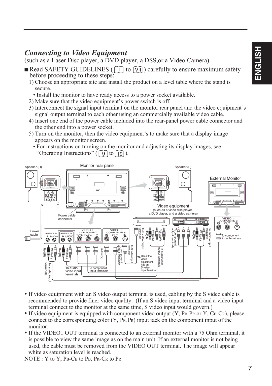
3)Interconnect the signal input terminal on the monitor rear panel and the video equipment’s signal output terminal to each other using an commercially available video cable.
4)Insert one end of the power cable included into the
5)Turn on the monitor, then the video equipment’s to make sure that a display image appears on the monitor screen.
•For instructions on turning on the monitor and adjusting its display images, see “Operating Instructions” ( 9 to 19 ).
ENGLISH
Speaker (R) |
|
|
|
|
|
|
|
| Monitor rear panel | ||||||
|
|
|
|
|
|
|
|
|
|
|
|
|
|
|
|
|
|
|
|
|
|
|
|
|
|
|
|
|
|
|
|
|
|
|
|
|
|
|
|
|
|
|
|
|
|
|
|
|
|
|
|
|
|
|
|
|
|
|
|
|
|
|
|
|
|
|
|
|
|
|
|
|
|
|
|
|
|
|
|
|
|
|
|
|
|
|
|
|
|
|
|
|
|
|
|
|
|
|
|
|
|
|
|
|
|
|
|
|
|
|
|
|
|
|
|
|
|
|
|
|
|
|
|
|
|
|
|
|
|
|
|
|
|
|
|
|
|
|
|
|
|
|
|
|
|
|
|
|
|
|
|
|
|
|
|
|
|
|
|
|
|
|
|
|
|
|
|
|
|
|
|
|
|
|
|
Power cable connector
Speaker (L)
External Monitor
Video equipment
(such as a video disc player,
a DVD player, and a video camera)
VIDEO 1
COMPOSITE S
IN OUT IN
Power |
|
| VIDEO 2 |
| VIDEO 1 | |
cable | AUDIO IN | AUDIO IN | COMPONENT | COMPOSITE S | ||
PR/CR PB/CB | Y | IN OUT IN | ||||
R L/MONO | R L/MONO | |||||
|
|
|
| |||
To S video terminals | Red(R) | White(L) | Yellow(V) | Tocomponent outputterminals |
To component ![]() input terminals
input terminals
Red(R) | White(L) | Red(R) | White(L) |
terminals | Toaudioinput |
| To audio/ |
|
|
| video input |
|
|
| terminals |
Yellow(V) |
|
|
|
|
|
|
| To component output terminals |
|
| To S video input terminals |
|
|
|
|
|
|
|
|
| |||
|
|
|
|
|
|
|
|
| |||
|
|
|
|
|
|
|
|
To component input terminals
Use if the video equipment has an
output | To audio/video outputterminals |
S video input terminal
•If video equipment with an S video output terminal is used, cabling by the S video cable is recommended to provide finer video quality. (If an S video input terminal and a video input terminal connect to the monitor at the same time, S video input would govern.)
•If video equipment is equipped with component video output (Y, PB, PR or Y, CB, CR), please connect to the corresponding color (Y, PB, PR) input jack on the component input of the monitor.
•If the VIDEO1 OUT terminal is connected to an external monitor with a 75 Ohm terminal, it is possible to view the same image as on the main unit. If an external monitor is not being used, the cable must be removed from the VIDEO OUT terminal. The image will appear white as saturation level is reached.
NOTE : Y to Y,
7