Manuals
/
Hitachi
/
Computer Equipment
/
Server
Hitachi
8880R
manual
Memory and CPU Slots, CPU/VRM Installation Detail
Models:
8880R
1
18
62
62
Download
62 pages
10.5 Kb
15
16
17
18
19
20
21
22
Specification
Install
Password
Errors and Countermeasures
Reset Configuration Data
Accessing the PCI Slots
Outline of the Setup Menu
Backup for ICU Disk
Jumper Settings
Load Setup Defaults
Page 18
Image 18
Page 17
Page 19
Page 18
Image 18
Page 17
Page 19
Contents
Hitachi VisionBase 8880R Server
Product Guide
Disclaimer
Copyright
Trademarks
Issue Date November Part Number 202-85031-01-Rev A
Contents
3 Error Information POST Error System Beeps
System Specifications
1 Hardware
System Overview
6 SCA2 Disk Bay SAF-TE Hot-swappable disk bay compliant SCSI
Ch 1 Hardware
Powering-On the System
Figure 1 Accessing the Power Supplies
Figure 2 Accessing the Power Supplies
Figure 3 P/S Receptacle and On/Off Switch
Front Panel
Figure 4 Front Panel Detail
Figure 5 Back Panel Detail
Figure 6 Direct Boot Switch Detail
Back Panel
Detail A
Warnings and Cautions
Removing the Server Panels and Accessing Its Components
Safety Guidelines
Tools and Supplies You Need
Accessing the PCI Slots
Figure 7 Accessing the Option Slots
PCI/ISA Option Boards
Figure 8 Option Slots
SCSI SCA Hard Disk Drives
Figure 9 Accessing the Hard Disk Drives
Hard Disk Drives
Figure 10 Hard Disk Drive Bays
Installing/Swapping a HDD
Figure 11 Removing/Installing a HDD
Optional Devices
Figure 12 Mounting the HDD Carrier
HDD HDD Position Pins HDD Carrier 4 Mounting Screws
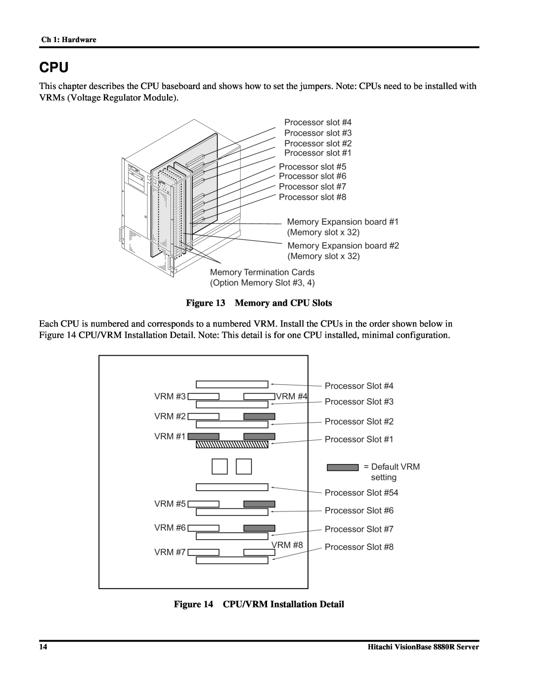
Figure 14 CPU/VRM Installation Detail
Figure 13 Memory and CPU Slots
Memory
Figure 15 Memory Board Slot Location
The system supports the following specifications for memory DIMMs
VRM #3
Jumper Settings
Figure 16 System Board Default Jumper Settings
VRM #4
Figure 17 I/O Board Switch Settings
2 System Environment Setting
Flow of System Environment Setting
Before Operations
What You Can Do with the System Environment Setting
Outline of the Setup Menu
Notes on Use
Outline of ISA Configuration Utility ICU
Setting for Each Board
PCI Board
Setup Menu
Flow of the Setup Menu Operation
Starting the Setup Menu
Figure 18 Entering Setup Menu
Setup Menu Screen
Configuration of the Setup Menu Screen
Figure 19 Setup Menu Screen Configuration
Operating the Keys on the Setup Menu
In the Setup Menu, the following key operations are allowed
Steps for Setting the Setup Menu
What You Can Do on the Main Menu
Figure 20 Main Menu Screen
System Time and System Date
Legacy Diskette A,B
Primary Master Slave
What You Can Do on the Advanced Menu
Reset Configuration Data
Execute ROM Diagnostic Unsupported
Network server
Select Resources
PCI Configuration
I/O Device Configuration
Current Resources
Local Bus IDE adapter
Parallel port
Floppy disk controller
PS/2 Mouse
Console Redirection Unsupported
Ext MP Configuration Table
Enable memory gap
I/O APIC Mode
Speaker Volume
WinNT 4.0 Install Mode
Large Disk Access Mode Unsupported
Caching Above 4GB
Set Supervisor Password
Supervisor Password is
User Password is
Set User Password
What You Can Do on the Boot menu
Figure 23 Boot Menu Screen
Hard Drive IDE Hard Disk Drive
Exit Discarding Changes
What You Can Do on the Exit Menu
Exit Saving Changes
Figure 24 Exit Menu Screen
Load Setup Defaults
ISA Configuration Utility ICU
Notes on the Setup Menu
Discard Changes
Backup for ICU Disk
Flow of Operation with the ICU
Space
System Resources
Starting the ICU
Do not remove ICU DISK2 before the ICU terminates
Operating the ICU
How to Use Help
ICU Screen
Figure 25 ICU Screen
Exiting the ICU
Checking Resource Status
Checking Resources Used by the System
Adding an Extended Board
Checking Resources for Extended Boards
6. A dialog box for confirmation is displayed. Choose OK
Changing the Settings in Extended Boards
Settings for Each Resource
Reserving I/O Port Addresses
Removing an Extended Board
When ICU Program Disk Has Been Destroyed
Reserving Resources In Use from an ISA Board
NOTE Unknown Card is displayed for RAID controller PC-CA7112
Restoring Configuration Information
Lock/Unlock Card
Errors and Countermeasures
Restrictions on the ICU
Returning the ICU Settings to Defaults
Returning the Settings to Defaults
Returning the Settings of the Setup Information to Defaults
List of Utility Settings
Fixed Configuration
Ch 2 System Environment Setting
Symbios Logic SCSI Configuration Utilities
This table defines the SCSI Select factory default settings
Ch 3 Error Information
3 Error Information
POST Error
Hitachi VisionBase 8880R
System Beeps
4 NT Drivers and Limitations
Installing Windows NT
2. Select Advanced Menu-Windows NT 4.0 Install Mode
Windows NT Driver Recommendations
Ch 4 NT Drivers and Limitations
5 Related Document and Specification
Environment Specification
Related Document
Ch 5 Related Document and Specification
Hitachi VisionBase 8880R
Top
Page
Image
Contents