English
PREPARATION BEFORE OPERATION
Make the following preparations before operating the power tool:
1. Installation
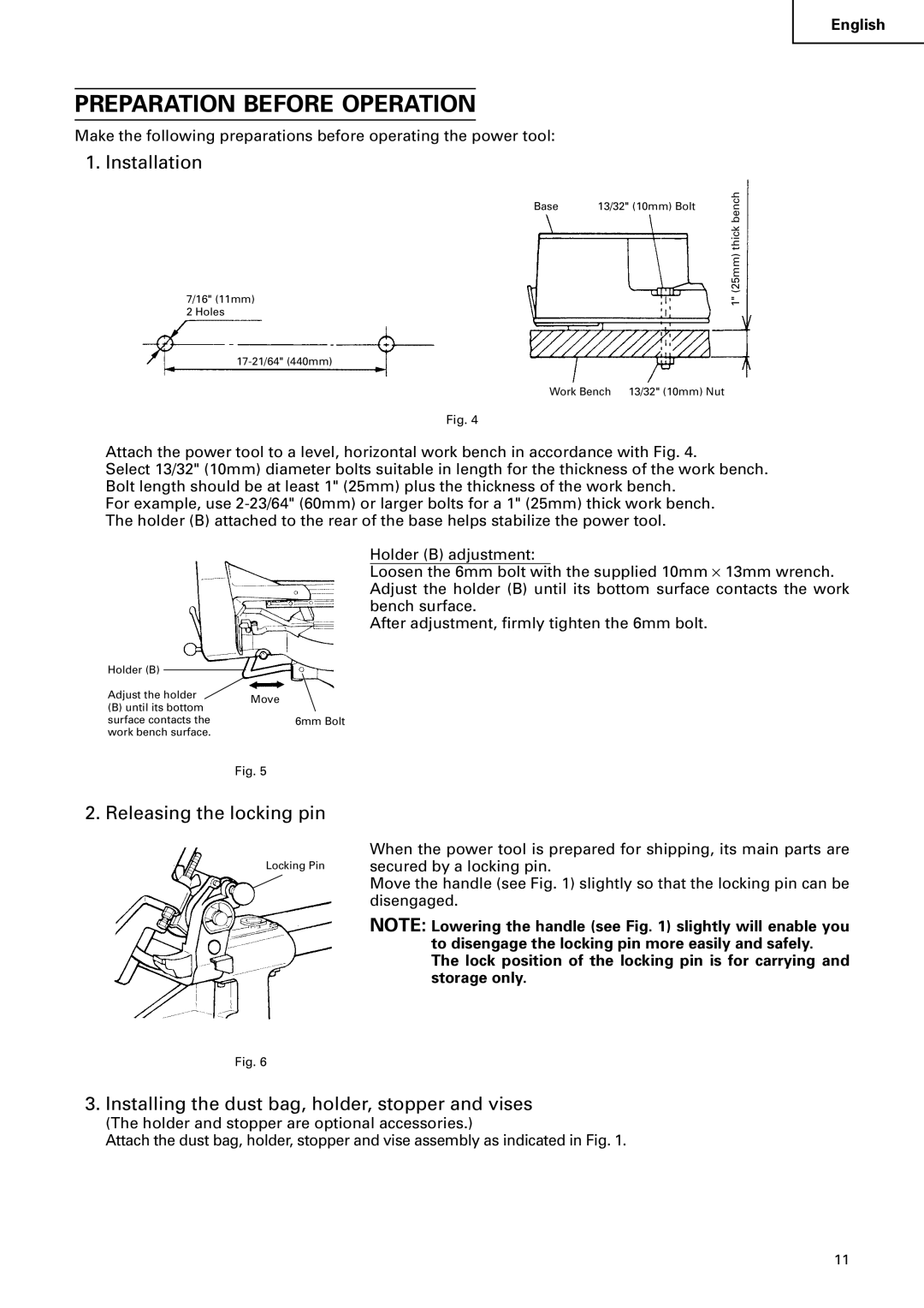
7/16" (11mm) 2 Holes
Base | benchthick(25mm)1" |
13/32" (10mm) Bolt |
Work Bench 13/32" (10mm) Nut
Fig. 4
Attach the power tool to a level, horizontal work bench in accordance with Fig. 4.
Select 13/32" (10mm) diameter bolts suitable in length for the thickness of the work bench. Bolt length should be at least 1" (25mm) plus the thickness of the work bench.
For example, use
Holder (B) adjustment:
Loosen the 6mm bolt with the supplied 10mm ⋅ 13mm wrench. Adjust the holder (B) until its bottom surface contacts the work bench surface.
After adjustment, firmly tighten the 6mm bolt.
Holder (B) |
| |
Adjust the holder | Move | |
(B) until its bottom | ||
| ||
surface contacts the | 6mm Bolt | |
work bench surface. |
| |
| Fig. 5 |
2. Releasing the locking pin
Locking Pin
When the power tool is prepared for shipping, its main parts are secured by a locking pin.
Move the handle (see Fig. 1) slightly so that the locking pin can be disengaged.
NOTE: Lowering the handle (see Fig. 1) slightly will enable you to disengage the locking pin more easily and safely.
The lock position of the locking pin is for carrying and storage only.
Fig. 6
3. Installing the dust bag, holder, stopper and vises
(The holder and stopper are optional accessories.)
Attach the dust bag, holder, stopper and vise assembly as indicated in Fig. 1.
11