English
8. Miter cutting procedures
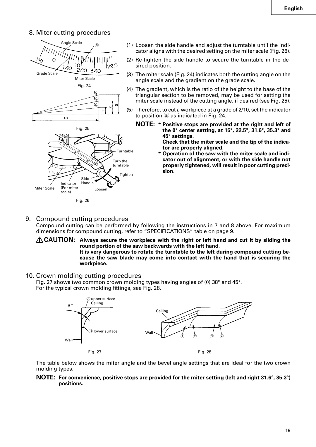
Angle Scale
Grade Scale
a
(1) | Loosen the side handle and adjust the turntable until the indi- |
| cator aligns with the desired setting on the miter scale (Fig. 26). |
(2) | |
| sired position. |
(3) | The miter scale (Fig. 24) indicates both the cutting angle on the |
Miter Scale
Fig. 24
| angle scale and the gradient on the grade scale. |
(4) | The gradient, which is the ratio of the height to the base of the |
| triangular section to be removed, may be used for setting the |
| miter scale instead of the cutting angle, if desired (see Fig. 25). |
(5) | Therefore, to cut a workpiece at a grade of 2/10, set the indicator |
| to position a as indicated in Fig. 24. |
Fig. 25
|
| Side |
| Indicator | Handle |
Miter Scale | (For miter | Loosen |
| scale) |
|
![]() Turntable
Turntable
Turn the turntable
Tighten
NOTE: * Positive stops are provided at the right and left of the 0° center setting, at 15°, 22.5°, 31.6°, 35.3° and 45° settings.
Check that the miter scale and the tip of the indica- tor are properly aligned.
*Operation of the saw with the miter scale and indi- cator out of alignment, or with the side handle not properly tightened, will result in poor cutting preci- sion.
Fig. 26
9. Compound cutting procedures
Compound cutting can be performed by following the instructions in 7 and 8 above. For maximum dimensions for compound cutting, refer to “SPECIFICATIONS” table on page 9.
![]() CAUTION: Always secure the workpiece with the right or left hand and cut it by sliding the round portion of the saw backwards with the left hand.
CAUTION: Always secure the workpiece with the right or left hand and cut it by sliding the round portion of the saw backwards with the left hand.
It is very dangerous to rotate the turntable to the left during compound cutting be- cause the saw blade may come into contact with the hand that is securing the workpiece.
10. Crown molding cutting procedures
Fig. 27 shows two common crown molding types having angles of (θ ) 38° and 45°. For the typical crown molding fittings, see Fig. 28.
Aupper surface Ceiling
Ceiling
B lower surface | Wall |
|
q w e r
Wall
Fig. 27 | Fig. 28 |
The table below shows the miter angle and the bevel angle settings that are ideal for the two crown molding types.
NOTE: For convenience, positive stops are provided for the miter setting (left and right 31.6°, 35.3°) positions.
19