English
3. Checking the saw blade lower limit position
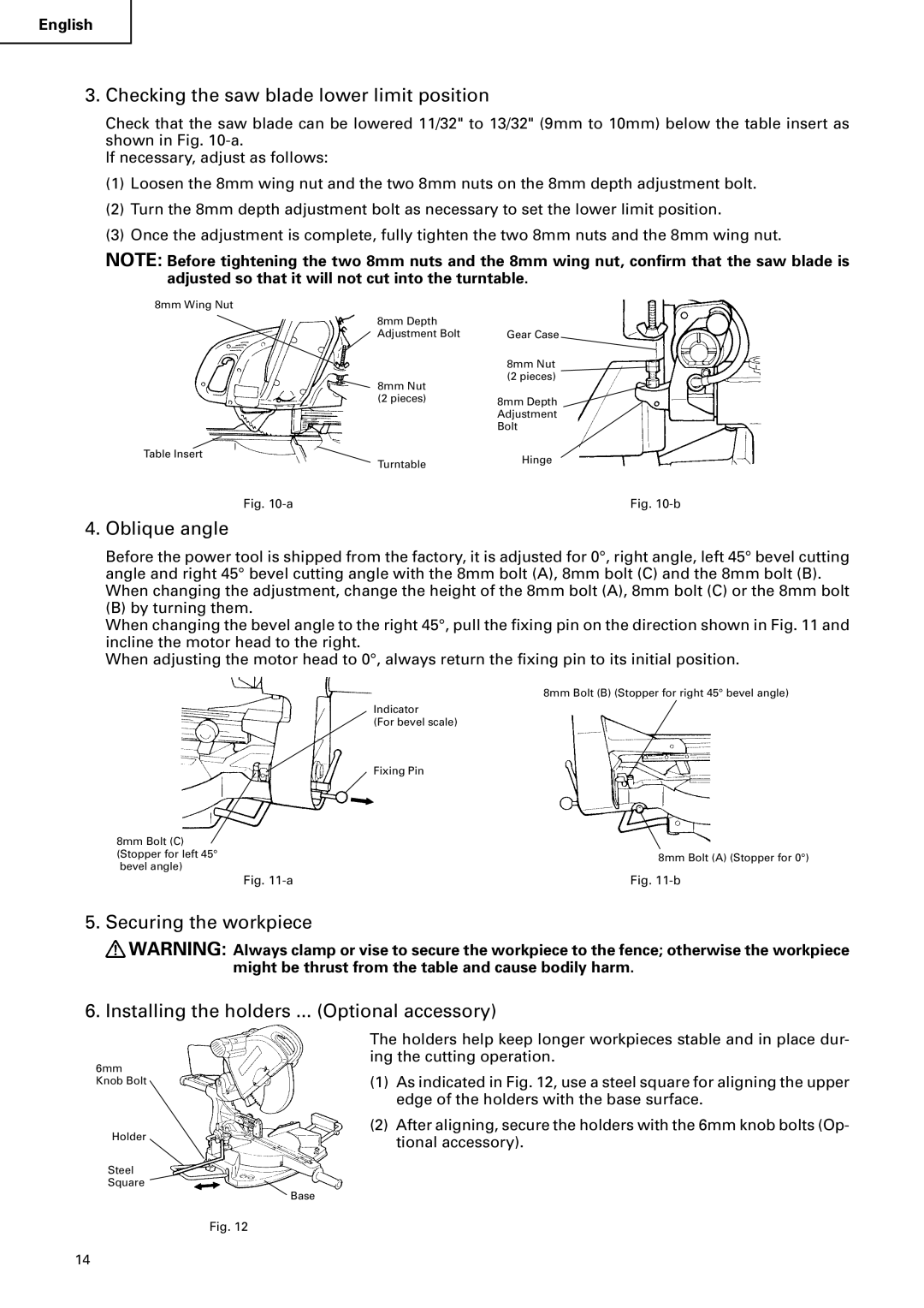
Check that the saw blade can be lowered 11/32" to 13/32" (9mm to 10mm) below the table insert as shown in Fig.
If necessary, adjust as follows:
(1)Loosen the 8mm wing nut and the two 8mm nuts on the 8mm depth adjustment bolt.
(2)Turn the 8mm depth adjustment bolt as necessary to set the lower limit position.
(3)Once the adjustment is complete, fully tighten the two 8mm nuts and the 8mm wing nut.
NOTE: Before tightening the two 8mm nuts and the 8mm wing nut, confirm that the saw blade is adjusted so that it will not cut into the turntable.
8mm Wing Nut
8mm Depth |
|
Adjustment Bolt | Gear Case |
Table Insert
8mm Nut
(2 pieces)
8mm Nut
(2 pieces)8mm Depth Adjustment Bolt
TurntableHinge
Fig. | Fig. |
4. Oblique angle
Before the power tool is shipped from the factory, it is adjusted for 0°, right angle, left 45° bevel cutting angle and right 45° bevel cutting angle with the 8mm bolt (A), 8mm bolt (C) and the 8mm bolt (B). When changing the adjustment, change the height of the 8mm bolt (A), 8mm bolt (C) or the 8mm bolt
(B) by turning them.
When changing the bevel angle to the right 45°, pull the fixing pin on the direction shown in Fig. 11 and incline the motor head to the right.
When adjusting the motor head to 0°, always return the fixing pin to its initial position.
8mm Bolt (C) (Stopper for left 45° bevel angle)
8mm Bolt (B) (Stopper for right 45° bevel angle)
Indicator
(For bevel scale)
Fixing Pin
8mm Bolt (A) (Stopper for 0°)
Fig. | Fig. |
5.Securing the workpiece
![]() WARNING: Always clamp or vise to secure the workpiece to the fence; otherwise the workpiece
WARNING: Always clamp or vise to secure the workpiece to the fence; otherwise the workpiece
might be thrust from the table and cause bodily harm.
6. Installing the holders ... (Optional accessory)
6mm Knob Bolt
Holder
Steel
Square
The holders help keep longer workpieces stable and in place dur- ing the cutting operation.
(1)As indicated in Fig. 12, use a steel square for aligning the upper edge of the holders with the base surface.
(2)After aligning, secure the holders with the 6mm knob bolts (Op- tional accessory).
Base
Fig. 12
14