English
(3)Setting to cut crown moldings at positions q and r in Fig. 28 (see Fig. 33; tilt the head to the right): q Turn the turntable to the right and set the Miter Angle as follows:
* For 45°type crown moldings: 35.3° ( |
| mark) |
* For 38°type crown moldings: 31.6° ( |
| mark) |
|
wTilt the head to the right and set the Bevel Angle as follows:
* For 45°type crown moldings: 30° ( |
| mark) | |
* For 38°type crown moldings: 33.9° ( |
| mark) | |
| |||
ePosition the crown molding so that the upper surface (B in Fig. 27) contacts the fence as indicated Fig. 34.
(4)Setting to cut crown moldings at positions w and e in Fig. 28 (see Fig. 33; tilt the head to the right): q Turn the turntable to the left and set the Miter Angle as follows:
*For 45°type crown moldings: 35.3° ( mark)
* For 38°type crown moldings: 31.6° ( mark)
wTilt the head to the right and set the Bevel Angle as follows:
* For 45°type crown moldings: 30° ( |
| mark) | |
* For 38°type crown moldings: 33.9° ( |
| mark) | |
| |||
ePosition the crown molding so that the lower surface (A in Fig. 27) contacts the fence as in Fig. 36.
Head |
| Head |
|
r | Bevel Angle Scale |
|
|
|
| Bevel Angle Scale | |
|
|
| |
| q | e | w |
|
|
| |
| Fence | Fence |
|
| Base |
| Base |
Miter Angle |
|
| |
Turntable | Turntable | Miter Angle | |
Scale |
|
| Scale |
| Fig. 33 |
| Fig. 35 |
Fence |
| Fence |
|
|
|
| |
B | A | A | B |
| |||
| Table on Base |
| Table on Base |
| Fig. 34 |
| Fig. 36 |
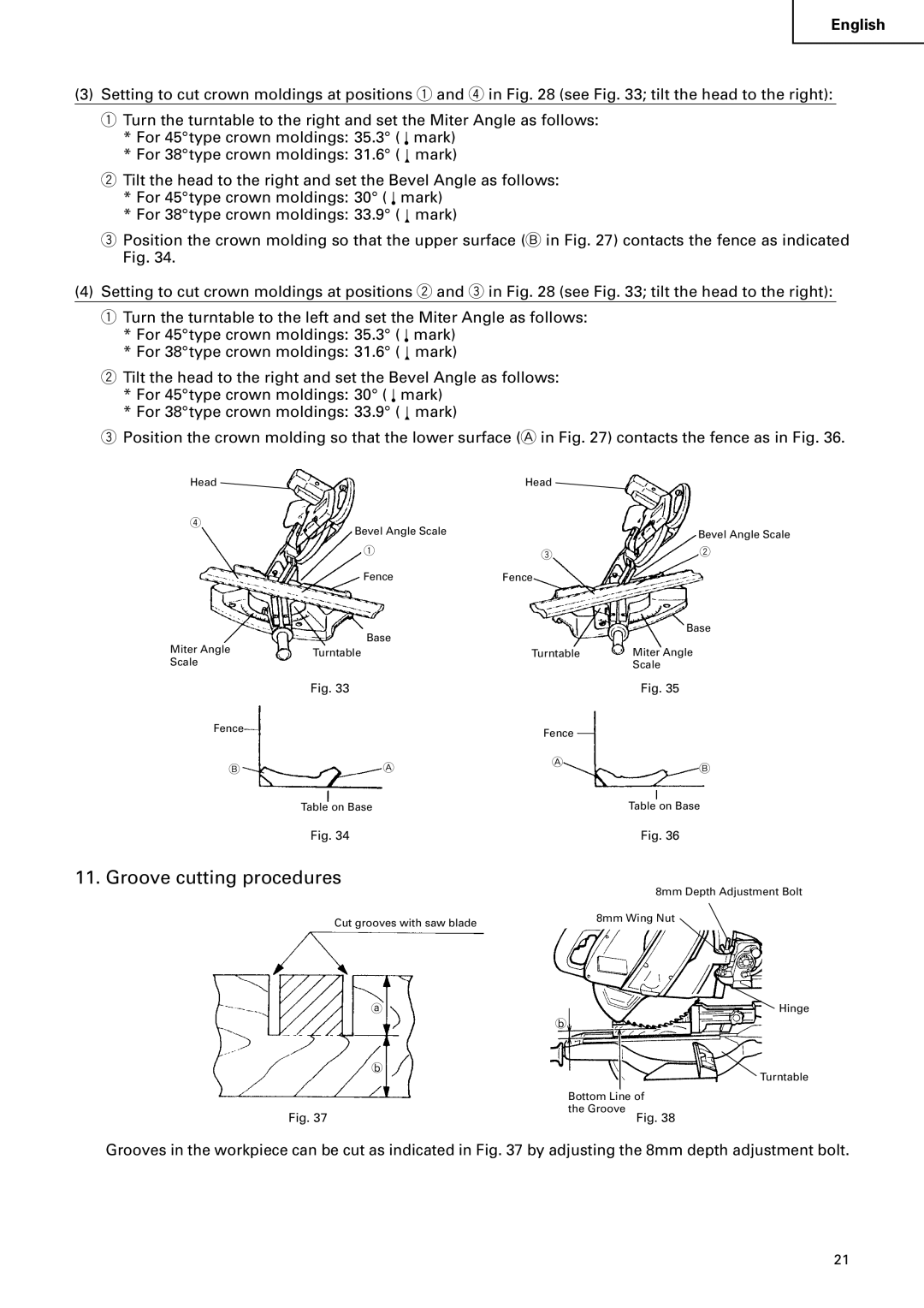
11. Groove cutting procedures
| 8mm Depth Adjustment Bolt |
Cut grooves with saw blade | 8mm Wing Nut |
| |
a | Hinge |
| b |
b | Turntable |
| |
| Bottom Line of |
Fig. 37 | the Groove |
Fig. 38 |
Grooves in the workpiece can be cut as indicated in Fig. 37 by adjusting the 8mm depth adjustment bolt.
21