English
Type of | To process crown molding at | To process crown molding at | |||||||||||||
Crown Molding | positions 1 and 4 in Fig. 25. | positions 2 and 3 in Fig. 25. | |||||||||||||
|
|
|
|
|
|
|
|
|
|
| |||||
| Miter Angle |
| Bevel Angle | Miter Angle |
| Bevel Angle | |||||||||
|
| Setting |
|
|
| Setting | Setting |
|
|
| Setting | ||||
|
|
|
|
|
|
|
|
|
|
|
|
|
| ||
45° Type | right | 35.3° | left 30° | right 30° | left 35.3° | left 30° | right 30° | ||||||||
|
|
|
|
|
|
|
|
|
|
|
|
|
| ||
38° Type | right | 31.6° | left 33.9° | right 33.9° | left 31.6° | left 33.9° | right 33.9° | ||||||||
|
|
| ( |
| mark) | ( |
| mark) |
| ( |
| mark) | ( |
| mark) |
|
|
|
|
|
|
|
| ||||||||
|
|
|
|
|
|
|
|
|
|
|
|
|
|
|
|
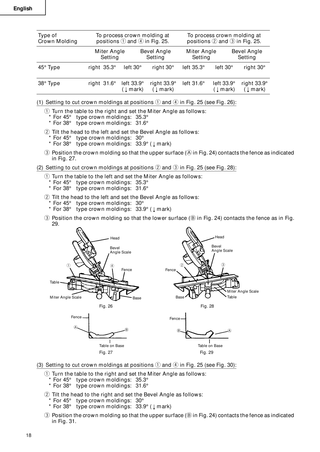
(1) Setting to cut crown moldings at positions q and r in Fig. 25 (see Fig. 26):
qTurn the table to the right and set the Miter Angle as follows:
*For 45° type crown moldings: 35.3°
*For 38° type crown moldings: 31.6°
wTilt the head to the left and set the Bevel Angle as follows:
*For 45° type crown moldings: 30°
*For 38° type crown moldings: 33.9° ( mark)
ePosition the crown molding so that the upper surface (A in Fig. 24) contacts the fence as indicated in Fig. 27.
(2)Setting to cut crown moldings at positions w and e in Fig. 25 (see Fig. 28):
qTurn the table to the left and set the Miter Angle as follows:
*For 45° type crown moldings: 35.3°
*For 38° type crown moldings: 31.6°
wTilt the head to the left and set the Bevel Angle as follows:
*For 45° type crown moldings: 30°
*For 38° type crown moldings: 33.9° ( mark)
ePosition the crown molding so that the lower surface (B in Fig. 24) contacts the fence as in Fig. 29.
| Head |
| Head |
|
|
| |
| Bevel |
| Bevel |
|
| Angle Scale | |
| Angle Scale |
| |
|
|
| |
q | r | w | e |
| Fence | Fence |
|
Table
Miter Angle Scale
Miter Angle Scale | Base | Base | Table |
| Fig. 26 |
| Fig. 28 |
Fence |
| Fence |
|
|
|
| |
A | B | B | A |
| |||
| Table on Base |
| Table on Base |
| Fig. 27 |
| Fig. 29 |
(3) Setting to cut crown moldings at positions q and r in Fig. 25 (see Fig. 30):
qTurn the table to the right and set the Miter Angle as follows:
*For 45° type crown moldings: 35.3°
*For 38° type crown moldings: 31.6°
wTilt the head to the right and set the Bevel Angle as follows:
*For 45° type crown moldings: 30°
*For 38° type crown moldings: 33.9° ( mark)
ePosition the crown molding so that the upper surface (B in Fig. 24) contacts the fence as indicated in Fig. 31.
18
