Code


Function Name


Monitored data or setting


A094


Select method to switch to Acc2/Dec2 profile


00

(switching by 2CH terminal), 01 (switching by setting),


02

(switching only when rotation is reversed)


A294


Select method to switch to Acc2/Dec2, 2nd motor


00

(switching by 2CH terminal), 01 (switching by setting),


adjustment


02

(switching only when rotation is reversed)


A095


Acc1 to Acc2 frequency transition point


0.00 to 99.99, 100.0 to 400.0 (Hz) (*1)


A296


Dec1 to Dec2 frequency transition point, 2nd motor


0.00 to 99.99, 100.0 to 400.0 (Hz) (*1)


A295


Acc1 to Acc2 frequency transition point, 2nd motor


0.00 to 99.99, 100.0 to 400.0 (Hz) (*1)


A096


Dec1 to Dec2 frequency transition point


0.00 to 99.99, 100.0 to 400.0 (Hz) (*1)


frequency

A097


Acceleration curve selection


00

(linear), 01 (S curve), 02 (U curve), 03 (inverted-U curve), 04 (EL-S curve)


A102


OI-L input active range end frequency


0.00 to 99.99, 100.0 to 400.0 (Hz) (*1)


A098


Deceleration curve selection


00

(linear), 01 (S curve), 02 (U curve), 03 (inverted-U curve), 04 (EL-S curve)


External

A101


OI-L input active range start frequency


0.00 to 99.99, 100.0 to 400.0 (Hz) (*1)


A105


OI-L input start frequency enable


00

(external start frequency), 1 (0 Hz)


A103


OI-L input active range start current


0. to "[OI]-[L] input active range end current" (%)


A104


OI-L input active range end current


"[OI]-[L] input active range start current" to 100. (%)


A111


O2-L input active range start frequency


-400. to -100., -99.9 to 0.00 to 99.99, 100.0 to 400.0 (Hz) (*2)


A112


O2-L input active range end frequency


-400. to -100., -99.9 to 0.00 to 99.99, 100.0 to 400.0 (Hz) (*2)


A113


O2-L input active range start voltage


-100. to 02 end-frequency rate (%)


and

A114


O2-L input active range end voltage


"02 start-frequency rate" to 100. (%)


A131


Acceleration curve constants setting


01

(smallest swelling) to 10 (largest swelling)

Acceleration deceleration

A132


Deceleration curve constants setting


01

(smallest swelling) to 10 (largest swelling)

frequency

A141


Operation-target frequency selection 1


00

(digital operator), 01 (keypad potentiometer), 02 (input via O), 03 (input via OI),


04

(external communication), 05 (option 1), 06 (option 2), 07 (pulse-string frequency input)


Operation-target

A142


Operation-target frequency selection 2


00

(digital operator), 01 (keypad potentiometer), 02 (input via O), 03 (input via OI),


04

(external communication), 05 (option 1), 06 (option 2), 07 (pulse-string frequency input)

A143


Operator selection


00 (addition: A141 + A142), 01 (subtraction: A141 - A142), 02 (multiplication: A141 x A142)


A145


Frequency to be added


0.00 to 99.99, 100.0 to 400.0 (Hz) (*1)


deceleration

A146


Sign of the frequency to be added


00

(frequency command + A145), 01 (frequency command - A145)


A150


EL-S-curve acceleration ratio 1


0. to 50. (%)


A152


EL-S-curve deceleration ratio 1


0. to 50. (%)

Acceleration

A151


EL-S-curve acceleration ratio 2


0. to 50. (%)


and

A153


EL-S-curve deceleration ratio 2


0. to 50. (%)


(*1)

4000HF:0.00 to 99.99, 100.0 to 120.0(Hz) (*2) -


120. to -100., -99.9 to 0.00 to 99.99 ,100.0 to 120.0(Hz)

B GROUP: FINE TUNING FUNCTIONS


Function Name


Monitored data or setting

Code

ortripping


b001


Selection of restart mode


00 (tripping), 01 (starting with 0 Hz), 02 (starting with matching frequency), 03 (tripping after


deceleration and stopping with matching frequency), 04 (restarting with active matching frequency)


b002


Allowable under-voltage power failure time


0.3 to 25.0 (s)


failure


b003


Retry wait time before motor restart


0.3 to 100.0 (s)


b004


Instantaneous power failure/under-voltage


00 (disabling), 01 (enabling), 02 (disabling during stopping and decelerating to stop)


trip alarm enable


power


b005


Number of restarts on power


00 (16 times), 01 (unlimited)


failure/under-voltage trip events


instantaneous


b006


Phase loss detection enable


00 (disabling), 01 (enabling)


b007


Restart frequency threshold


0.00 to 99.99, 100.0 to 400.0 (Hz) (*2)


b008


Selection of retry after tripping


00 (tripping), 01 (starting with 0 Hz), 02 (starting with matching frequency), 03 (tripping after


deceleration and stopping with matching frequency), 04 (restarting with active matching frequency)


after


b009


Selection of retry after undervoltage


00 (16 times), 01 (unlimited)


Selection of retry count after overvoltage


Restart


b010


1 to 3 (times)


or overcurrent


b011


Retry wait time after tripping


0.3 to 100.0 (s)


b012


Electronic thermal setting (calculated within


0.20 x "rated current" to 1.00 x "rated current" (A)


the inverter from current output)


function


b212


Electronic thermal setting (calculated within


0.20 x "rated current" to 1.00 x "rated current" (A)


the inverter from current output), 2nd motor


b312


Electronic thermal setting (calculated within


0.20 x "rated current" to 1.00 x "rated current" (A)


the inverter from current output), 3rd motor


thermal


b013


Electronic thermal characteristic


00 (reduced-torque characteristic), 01 (constant-torque characteristic), 02 (free setting)


b213


Electronic thermal characteristic, 2nd motor


00 (reduced-torque characteristic), 01 (constant-torque characteristic), 02 (free setting)


b313


Electronic thermal characteristic, 3rd motor


00 (reduced-torque characteristic), 01 (constant-torque characteristic), 02 (free setting)


Electronic


b015


Free-setting electronic thermal frequency (1)


0. to 400. (Hz)(*3)


b016


Free-setting electronic thermal current (1)


0.00 to rated current (A)


b017


Free-setting electronic thermal frequency (2)


0. to 400. (Hz)(*3)


b018


Free-setting electronic thermal current (2)


0.00 to rated current (A)


b019


Free-setting electronic thermal frequency (3)


0. to 400. (Hz)(*3)


b020


Free-setting electronic thermal current (3)


0.00 to rated current (A)


restraint


00 (disabling), 01 (enabling during acceleration and deceleration), 02 (enabling during


b021


Overload restriction operation mode


constant speed), 03 (enabling during acceleration and deceleration (increasing the speed


during regeneration))


overcurrent


b022


Overload restriction setting


SJ700: 0.20 x "rated current" to 2.00 x "rated current" (A) < 75kW and over:0.20 x 1.80 >


SJ700B: 0.20 x "rated current" to 1.50 x "rated current" (A)


b023


Deceleration rate at overload restriction


0.10 to 30.00 (s)


and


b024


Overload restriction operation mode (2)


00 (disabling), 01 (enabling during acceleration and deceleration), 02 (enabling during


restriction


constant speed), 03 (enabling during acceleration and deceleration (increasing the speed


during regeneration))


b025


Overload restriction setting (2)


SJ700: 0.20 x "rated current" to 2.00 x "rated current" (A) < 75kW and over:0.20 x 1.80 >


Overload


SJ700B: 0.20 x "rated current" to 1.50 x "rated current" (A)


b026


Deceleration rate at overload restriction (2)


0.10 to 30.00 (s)


b027


Overcurrent suppression enable


00 (disabling), 01 (enabling)


(*1)


4000HF:5.0 (*2) 4000HF:0.00 to 99.99,100.0 to 120.0 (Hz) (*3) 4000HF:0. to 120.(Hz)


[◯= Allowed×= Not permitted


Default Setting


Setting

Change


SJ700


during operation during operation

-FE(CE) -FU(UL) -F(JP) SJ700B

(allowed or not) (allowed or not)

00


00


00


00

×

×


00


00


00


00

×

×


0.00


0.00


0.00


0.00

×

×


0.00


0.00


0.00


0.00

×

×


0.00


0.00


0.00


0.00

×

×


0.00


0.00


0.00


0.00

×

×


00


00


00


00

×

×


00


00


00


00

×

×


0.00


0.00


0.00


0.00

×

×


0.00


0.00


0.00


0.00

×

20.


20.


20.


20.

×

100.


100.


100.


100.

×

00


00


00


00

×

0.00


0.00


0.00


0.00

×

0.00


0.00


0.00


0.00

×

-100.

-100.

-100.

-100.

×

100.


100.


100.


100.

×

02


02


02


02

×

02


02


02


02

×

02


02


02


02

×

03


03


03


03

×

00


00


00


00

×

0.00


0.00


0.00


0.00

×

00


00


00


00

×

25.


25.


25.


25.

×

×


25.


25.


25.


25.

×

×


25.


25.


25.


25.

×

×


25.


25.


25.


25.

×

×


[◯= Allowed×= Not permitted


Default Setting


Setting

Change


SJ700


during operation during operation

-FE(CE) -FU(UL) -F(JP) SJ700B

(allowed or not) (allowed or not)

00


00


00


00

×

1.0


1.0


1.0


1.0

×

1.0(*1)


1.0(*1)


1.0(*1)


1.0

×

00


00


00


00

×

00


00


00


00

×

00


00


00


00

×

0.00


0.00


0.00


0.00

×

00


00


00


00

×

00


00


00


00

×

3


3


3


3

×

1.0(*1)


1.0(*1)


1.0(*1)


1.0

×


×


Rated current of


×


inverterx 1..0


×

01


01


00


01

×


01


01


00


01

×

01


01


00


01

×

0.


0.


0.


0.

×

0.0


0.0


0.0


0.0

×

0.


0.


0.


0.

×

0.0


0.0


0.0


0.0

×

0.


0.


0.


0.

×

0.0


0.0


0.0


0.0

×

01


01


01


01

×


Rated

×

Rated current x 1.50


current


x 1.20

×

1.00


1.00


1.00


1.00

01


01


01


01

×


Rated

×

Rated current x 1.50


current


x 1.20

×

1.00


1.00


1.00


1.00

01


01


01


01

×


14

Page 15
Image 15
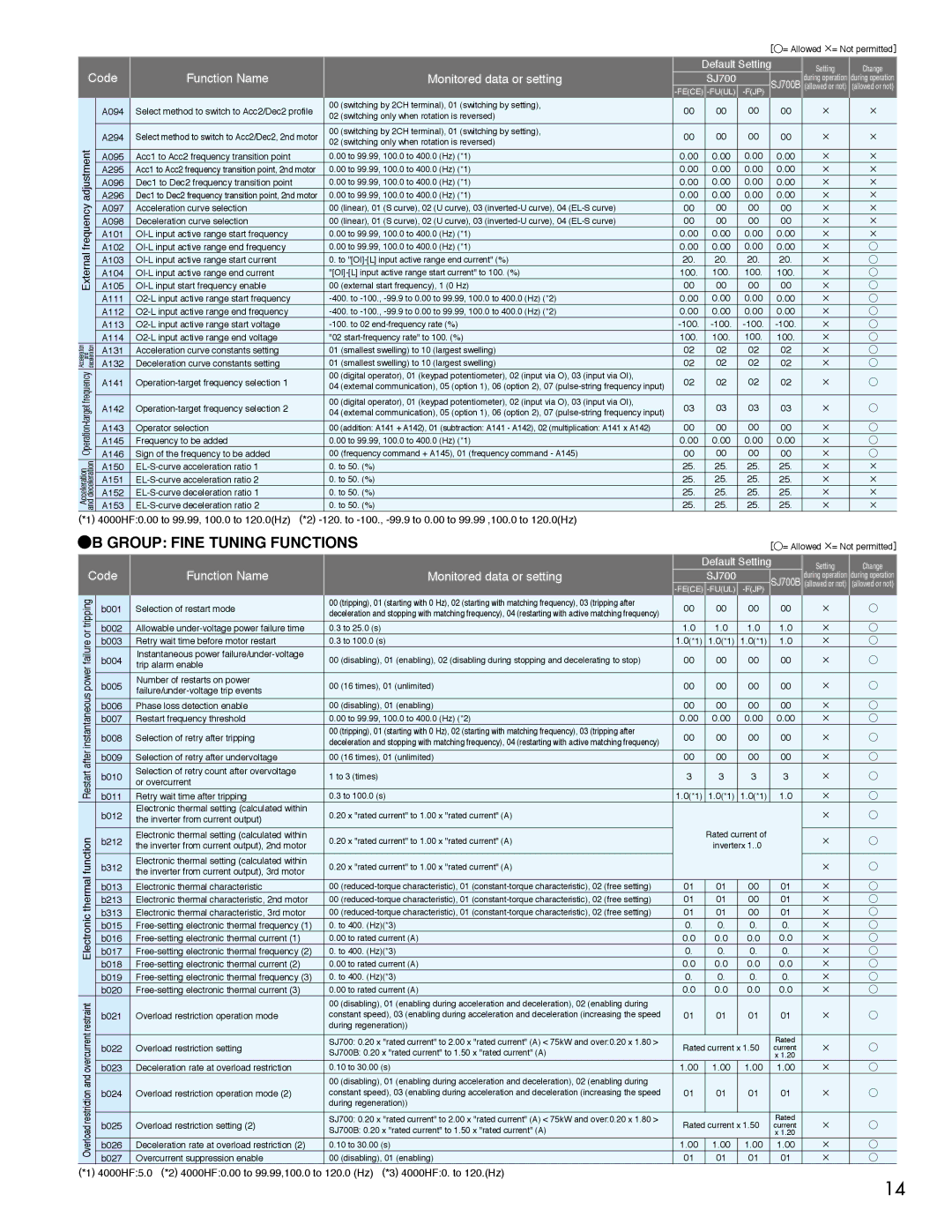
Hitachi SJ700B A094, A294, A095, A296, A295, A096, A097, A102, A098, A101, A105, A103, A104, A111, A112, A113, A114, A131

SJ700B, SJ700 specifications

The Hitachi SJ700 and SJ700B series are renowned variable frequency drives (VFDs) that represent a significant advancement in motor control technology. Designed for industrial applications, these drives offer a versatile solution for managing motor speed, torque, and efficiency in a variety of settings.

One of the main features of the SJ700 and SJ700B series is their compact design. This allows for easy installation and integration into existing systems, which is crucial for minimizing downtime during upgrades or replacements. The drives support multiple mounting orientations, facilitating applications with space constraints.

Another standout characteristic is their advanced control algorithms. The SJ700 series uses vector control technology, which optimizes the performance of both AC and induction motors. This ensures high precision in speed and torque control, making it suitable for processes that require fine adjustments. The drives also feature automatic tuning capabilities, which allow for quick commissioning while minimizing the need for extensive parameter adjustments.

The SJ700 and SJ700B series are designed with energy efficiency in mind. They utilize advanced regenerative braking technology that recovers energy, reducing power consumption and improving overall system efficiency. Furthermore, these drives incorporate energy-saving features that optimize motor operation based on load requirements, contributing to a lower carbon footprint.

These drives come equipped with robust communication capabilities. They support various communication protocols such as Modbus, Profibus, and EtherCAT, making them easily integrable with modern automation systems. This flexibility allows for real-time monitoring and control, enhancing operational visibility and efficiency.

Reliability is another hallmark of the SJ700 series. Built with high-quality components, these drives exhibit excellent thermal management and protection against overvoltage, overload, and short circuits. The SJ700B variant boasts additional features such as enhanced fault diagnostics and improved environmental protection, making it suitable for more demanding applications.

In conclusion, the Hitachi SJ700 and SJ700B series variable frequency drives stand out in terms of compact design, advanced control technologies, energy efficiency, versatile communication options, and robust reliability. These features make them an ideal choice for a wide range of industrial applications, from manufacturing automation to HVAC systems, ensuring optimal performance and cost savings for users.