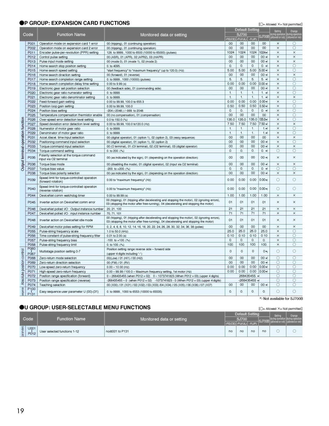
P GROUP: EXPANSION CARD FUNCTIONS

Code


Function Name


Monitored data or setting


P001


Operation mode on expansion card 1 error


00

(tripping), 01 (continuing operation)


P002


Operation mode on expansion card 2 error


00

(tripping), 01 (continuing operation)


P011


Encoder pulse-per-revolution (PPR) setting


128. to 9999., 1000 to 6500 (10000 to 65000) (pulses)


P012


Control pulse setting


00

(ASR), 01 (APR), 02 (APR2), 03 (HAPR)


P013


Pulse input mode setting


00

(mode 0), 01 (mode 1), 02 (mode 2)


P014


Home search stop position setting


0. to 4095.


P015


Home search speed setting


"start frequency" to "maximum frequency" (up to 120.0) (Hz)


P016


Home search direction setting


00

(forward), 01 (reverse)


P017


Home search completion range setting


0. to 9999., 1000 (10000) (pulses)


P018


Home search completion delay time setting


0.00 to 9.99 (s)


P019


Electronic gear set position selection


00

(feedback side), 01 (commanding side)


P020


Electronic gear ratio numerator setting


0. to 9999.


P021


Electronic gear ratio denominator setting


0. to 9999.


P022


Feed-forward gain setting


0.00 to 99.99, 100.0 to 655.3


P023


Position loop gain setting


0.00 to 99.99, 100.0


P024


Position bias setting


-204 (-2048.) / -999. to 2048

function

P025


Temperature compensation thermistor enable


00

(no compensation), 01 (compensation)

P026


Over-speed error detection level setting


0.0 to 150.0 (%)


P027


Speed deviation error detection level setting


0.00 to 99.99, 100.0 to120.0 (Hz)

operation

P028


Numerator of motor gear ratio


0. to 9999.

P029


Denominator of motor gear ratio


0. to 9999.


P031


Accel./decel. time input selection


00

(digital operator), 01 (option 1), 02 (option 2), 03 (easy sequence)


P032


Positioning command input selection


00

(digital operator), 01 (option 1), 02 (option 2)

terminal

P033


Torque command input selection


00

(O terminal), 01 (OI terminal), 02 (O2 terminal), 03 (digital operator)

P035


Polarity selection at the torque command


00

(as indicated by the sign), 01 (depending on the operation direction)


P034


Torque command setting


0. to 200. (%)

Output

P037


input via O2 terminal


-200. to +200. (%)


Torque bias value


P036


Torque bias mode


00

(disabling the mode), 01 (digital operator), 02 (input via O2 terminal)


P038


Torque bias polarity selection


00

(as indicated by the sign), 01 (depending on the operation direction)


P039


Speed limit for torque-controlled operation


0.00 to "maximum frequency" (Hz)


(forward rotation)


P040


Speed limit for torque-controlled operation


0.00 to "maximum frequency" (Hz)


(reverse rotation)


P044


DeviceNet comm watchdog timer


0.00 to 99.99 (s)


P045


Inverter action on DeviceNet comm error


00 (tripping), 01 (tripping after decelerating and stopping the motor), 02 (ignoring errors),


03 (stopping the motor after free-running), 04 (decelerating and stopping the motor)


P046


DeviceNet polled I/O : Output instance number


20, 21, 100


P047


DeviceNet polled I/O : input instance number


70, 71, 101


P048


Inverter action on DeviceNet idle mode


00 (tripping), 01 (tripping after decelerating and stopping the motor), 02 (ignoring errors),


03 (stopping the motor after free-running), 04 (decelerating and stopping the motor)


P049


DeviceNet motor poles setting for RPM


0, 2, 4, 6, 8, 10, 12, 14, 16, 18, 20, 22, 24, 26, 28, 30, 32, 34, 36, 38 (poles)


P055


Pulse-string frequency scale


1.0 to 50.0 (kHz)


P056


Time constant of pulse-string frequency filter


0.01 to 2.00 (s)


P057


Pulse-string frequency bias


-100. to +100. (%)


P058


Pulse-string frequency limit


0. to 100. (%)

control

P060


Position setting range reverse side – forward side

I


Multistage position setting 0-7


(upper 4 digits including “-“)


P067


position

P068


Zero-return mode selection


00(Low) / 01 (Hi1) / 00 (Hi2)

P069


Zero-return direction selection


00

(FW) / 01 (RV)


P070


Low-speed zero-return frequency


0.00 – 10.00 (Hz)

Absolute

P071


High-speed zero-return frequency


0.00 – 99.99 / 100.0 – Maximum frequency setting, 1st motor (Hz)

P072


Position range specification (forward)


0 – 268435455 (when P012 = 02) 0 – 1073741823 (When P012 = 03) (upper 4 digits)


P073


Position range specification (reverse)


-268435455 – 0 (when P012 = 02) -1073741823 - 0 (When P012 = 03) (upper 4 digits)

sequence

P074


Teaching selection


00

(X00) / 01 (X01) / 02 (X02) / 03 (X03) /04 (X04) / 05 (X05) / 06 (X06) / 07 (X07)

P100


Easy sequence user parameter U (00)-(31)


0. to 9999., 1000 to 6553 (10000 to 65535)

P131


I


[◯= Allowed×= Not permitted


Default Setting


Setting

Change


SJ700


during operation during operation


SJ700B (allowed or not) (allowed or not)

-FE(CE) -FU(UL) -F(JP)


00


00

00


00

×

00


00

00


00

×

1024


1024

1024


1024*)

×

×

00


00

00


00

*)

×

×

00


00

00


00

*)

×

×

0.


0.

0.


0.

*)

×

5.00


5.00

5.00


5.00

*)

×

00


00

00


00

*)

×

×

5.


5.

5.


5.

*)

×

0.00


0.00

0.00


0.00

*)

×

00


00

00


00

*)

×

1.


1.

1.


1.

*)

×

1.


1.

1.


1.

*)

×

×

0.00


0.00

0.00


0.00

*)

×

0.50


0.50

0.50


0.50

*)

×

0.


0.

0.


0.

*)

×

00


00

00


00

×

135.0

135.0

135.0

135.0*)

×

7.50


7.50

7.50


7.50

*)

×

×

1.


1.

1.


1.*)

×

1.


1.

1.


1.*)

×

00


00

00


00

×

×

00


00

00


00

*)

×

00


00

00


00

*)

×

×

0.


0.

0.


0. *)

00


00

00


00 *)

×

×

00


00

00


00

*)

×

×

0.


0.

0.


0.

*)

00


00

00


00 *)

×

×

0.00


0.00

0.00


0.00*)

0.00


0.00

0.00


0.00*)

1.00


1.00

1.00


1.00

×

×

01


01

01


01

×

×

21


21

21


21

×

×

71


71

71


71

×

×

01


01

01


01

×

×

00


00

00


00

×

×

25.0


25.0

25.0


25.0

×

0.10


0.10

0.10


0.10

×

0.


0.

0.


0.

×

100.


100.

100.


100.

×

0


0

0


0*)

00


00

00


00

*)

00


00

00


00

*)

0.00


0.00

0.00


0.00

*)

0.00


0.00

0.00


0.00

*)


268435455

*)


-268435455

*)


00

00

00

00 *)

0.

0.

0.

0.

*) Not available for SJ700B

U GROUP: USER-SELECTABLE MENU FUNCTIONS

[◯= Allowed×= Not permitted


Default Setting

Setting

Change

Code

Function Name

Monitored data or setting


no


during operation during operation


SJ700


SJ700B (allowed or not)

(allowed or not)


-FE(CE) -FU(UL)

-F(JP)

parameters

U001

User selected functions 1-12

no/d001 to P131

no

no

no

no

I

P012


19

Page 20
Image 20
Hitachi manual Output, Not available for SJ700B, 1024 135.0, 25.0 100

SJ700B, SJ700 specifications

The Hitachi SJ700 and SJ700B series are renowned variable frequency drives (VFDs) that represent a significant advancement in motor control technology. Designed for industrial applications, these drives offer a versatile solution for managing motor speed, torque, and efficiency in a variety of settings.

One of the main features of the SJ700 and SJ700B series is their compact design. This allows for easy installation and integration into existing systems, which is crucial for minimizing downtime during upgrades or replacements. The drives support multiple mounting orientations, facilitating applications with space constraints.

Another standout characteristic is their advanced control algorithms. The SJ700 series uses vector control technology, which optimizes the performance of both AC and induction motors. This ensures high precision in speed and torque control, making it suitable for processes that require fine adjustments. The drives also feature automatic tuning capabilities, which allow for quick commissioning while minimizing the need for extensive parameter adjustments.

The SJ700 and SJ700B series are designed with energy efficiency in mind. They utilize advanced regenerative braking technology that recovers energy, reducing power consumption and improving overall system efficiency. Furthermore, these drives incorporate energy-saving features that optimize motor operation based on load requirements, contributing to a lower carbon footprint.

These drives come equipped with robust communication capabilities. They support various communication protocols such as Modbus, Profibus, and EtherCAT, making them easily integrable with modern automation systems. This flexibility allows for real-time monitoring and control, enhancing operational visibility and efficiency.

Reliability is another hallmark of the SJ700 series. Built with high-quality components, these drives exhibit excellent thermal management and protection against overvoltage, overload, and short circuits. The SJ700B variant boasts additional features such as enhanced fault diagnostics and improved environmental protection, making it suitable for more demanding applications.

In conclusion, the Hitachi SJ700 and SJ700B series variable frequency drives stand out in terms of compact design, advanced control technologies, energy efficiency, versatile communication options, and robust reliability. These features make them an ideal choice for a wide range of industrial applications, from manufacturing automation to HVAC systems, ensuring optimal performance and cost savings for users.