TERMINALS

Control Circuit Terminals

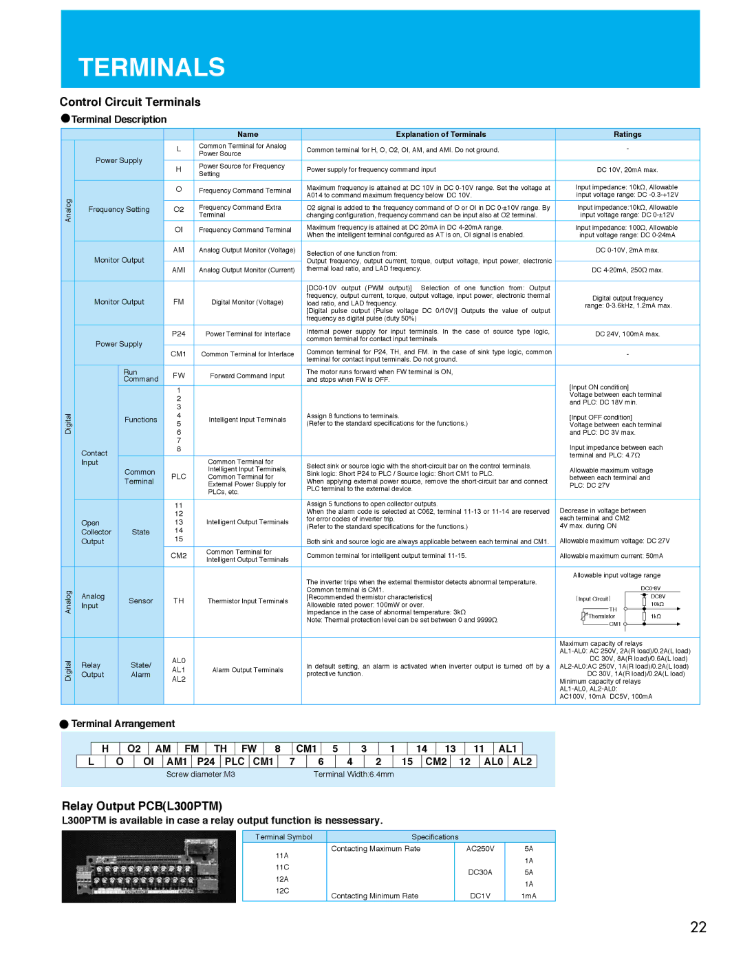
Terminal Description

Analog

Digital

DigitalAnalog


Symbol

Name

Explanation of Terminals


Ratings


L

Common Terminal for Analog

Common terminal for H, O, O2, OI, AM, and AMI. Do not ground.

-


Power Supply


Power Source


H

Power Source for Frequency

Power supply for frequency command input


DC 10V, 20mA max.


Setting


O

Frequency Command Terminal

Maximum frequency is attained at DC 10V in DC 0-10V range. Set the voltage at

Input impedance: 10kΩ, Allowable


A014 to command maximum frequency below DC 10V.

input voltage range: DC -0.3-+12V

Frequency Setting

O2

Frequency Command Extra

O2 signal is added to the frequency command of O or OI in DC 0-±10V range. By

Input impedance:10kΩ, Allowable


Terminal

changing configuration, frequency command can be input also at O2 terminal.

input voltage range: DC 0-±12V


OI

Frequency Command Terminal

Maximum frequency is attained at DC 20mA in DC 4-20mA range.

Input impedance: 100Ω, Allowable


When the intelligent terminal configured as AT is on, OI signal is enabled.

input voltage range: DC 0-24mA

Monitor Output

AM

Analog Output Monitor (Voltage)

Selection of one function from:


DC 0-10V, 2mA max.


Output frequency, output current, torque, output voltage, input power, electronic


AMI

Analog Output Monitor (Current)

thermal load ratio, and LAD frequency.


DC 4-20mA, 250Ω max.


[DC0-10V output (PWM output)] Selection of one function from: Output


Monitor Output

FM

Digital Monitor (Voltage)

frequency, output current, torque, output voltage, input power, electronic thermal


Digital output frequency

load ratio, and LAD frequency.


range: 0-3.6kHz, 1.2mA max.


[Digital pulse output (Pulse voltage DC 0/10V)] Outputs the value of output


frequency as digital pulse (duty 50%)


P24

Power Terminal for Interface

Internal power supply for input terminals. In the case of source type logic,


DC 24V, 100mA max.

Power Supply


common terminal for contact input terminals.


CM1

Common Terminal for Interface

Common terminal for P24, TH, and FM. In the case of sink type logic, common

-


terminal for contact input terminals. Do not ground.


Run

FW

Forward Command Input

The motor runs forward when FW terminal is ON,


Command

and stops when FW is OFF.


[Input ON condition]


1


2


Voltage between each terminal


and PLC: DC 18V min.


3


Functions

4

Intelligent Input Terminals

Assign 8 functions to terminals.

[Input OFF condition]


5


(Refer to the standard specifications for the functions.)

Voltage between each terminal


6


and PLC: DC 3V max.


7


Input impedance between each

Contact


8


terminal and PLC: 4.7Ω


Input


Common Terminal for

Select sink or source logic with the short-circuit bar on the control terminals.


Common


Intelligent Input Terminals,

Allowable maximum voltage


PLC

Sink logic: Short P24 to PLC / Source logic: Short CM1 to PLC.


Terminal

Common Terminal for

When applying external power source, remove the short-circuit bar and connect

between each terminal and


External Power Supply for

PLC: DC 27V


PLC terminal to the external device.


PLCs, etc.


11


Assign 5 functions to open collector outputs.

Decrease in voltage between


12


When the alarm code is selected at C062, terminal 11-13 or 11-14 are reserved


Open


13

Intelligent Output Terminals

for error codes of inverter trip.

each terminal and CM2:


(Refer to the standard specifications for the functions.)

4V max. during ON


Collector

State

14


Output


15


Both sink and source logic are always applicable between each terminal and CM1.

Allowable maximum voltage: DC 27V


CM2

Common Terminal for

Common terminal for intelligent output terminal 11-15.

Allowable maximum current: 50mA


Intelligent Output Terminals


The inverter trips when the external thermistor detects abnormal temperature.

Allowable input voltage range


DC0-8V


Analog


Common terminal is CM1.


Sensor

TH

Thermistor Input Terminals

[Recommended thermistor characteristics]

[Input Circuit]


DC8V


Input

Allowable rated power: 100mW or over.


TH


10kΩ


Impedance in the case of abnormal temperature: 3kΩ


1kΩ


Note: Thermal protection level can be set between 0 and 9999Ω.


Thermistor


CM1


Maximum capacity of relays


AL0


AL1-AL0: AC 250V, 2A(R load)/0.2A(L load)

Relay

State/


In default setting, an alarm is activated when inverter output is turned off by a


DC 30V, 8A(R load)/0.6A(L load)

AL1

Alarm Output Terminals

AL2-AL0:AC 250V, 1A(R load)/0.2A(L load)

Output

Alarm

protective function.


DC 30V, 1A(R load)/0.2A(L load)

AL2


Minimum capacity of relays


AL1-AL0, AL2-AL0:


AC100V, 10mA DC5V, 100mA

Terminal Arrangement

H

O2

AM FM TH FW

8

CM1 5

3

1

14 13

11 AL1

L

O

OI AM1 P24 PLC CM1

7

6

4

2

15 CM2 12

AL0 AL2


Screw diameter:M3


Terminal Width:6.4mm


Relay Output PCB(L300PTM)

L300PTM is available in case a relay output function is nessessary.

Terminal Symbol

Specifications


11A

Contacting Maximum Rate


AC250V

5A


1A

11C


DC30A


5A

12A


1A

12C

Contacting Minimum Rate


DC1V


1mA


22

Page 23
Image 23
Hitachi SJ700B manual Analog Digital DigitalAnalog, Run, Contact, Common, Terminal, Open, Collector, Sensor, Relay, 11C

SJ700B, SJ700 specifications

The Hitachi SJ700 and SJ700B series are renowned variable frequency drives (VFDs) that represent a significant advancement in motor control technology. Designed for industrial applications, these drives offer a versatile solution for managing motor speed, torque, and efficiency in a variety of settings.

One of the main features of the SJ700 and SJ700B series is their compact design. This allows for easy installation and integration into existing systems, which is crucial for minimizing downtime during upgrades or replacements. The drives support multiple mounting orientations, facilitating applications with space constraints.

Another standout characteristic is their advanced control algorithms. The SJ700 series uses vector control technology, which optimizes the performance of both AC and induction motors. This ensures high precision in speed and torque control, making it suitable for processes that require fine adjustments. The drives also feature automatic tuning capabilities, which allow for quick commissioning while minimizing the need for extensive parameter adjustments.

The SJ700 and SJ700B series are designed with energy efficiency in mind. They utilize advanced regenerative braking technology that recovers energy, reducing power consumption and improving overall system efficiency. Furthermore, these drives incorporate energy-saving features that optimize motor operation based on load requirements, contributing to a lower carbon footprint.

These drives come equipped with robust communication capabilities. They support various communication protocols such as Modbus, Profibus, and EtherCAT, making them easily integrable with modern automation systems. This flexibility allows for real-time monitoring and control, enhancing operational visibility and efficiency.

Reliability is another hallmark of the SJ700 series. Built with high-quality components, these drives exhibit excellent thermal management and protection against overvoltage, overload, and short circuits. The SJ700B variant boasts additional features such as enhanced fault diagnostics and improved environmental protection, making it suitable for more demanding applications.

In conclusion, the Hitachi SJ700 and SJ700B series variable frequency drives stand out in terms of compact design, advanced control technologies, energy efficiency, versatile communication options, and robust reliability. These features make them an ideal choice for a wide range of industrial applications, from manufacturing automation to HVAC systems, ensuring optimal performance and cost savings for users.