B. For CE Units
1 | 2 | 3 | 4 | 5 | 6 | 7 | 13 | 14 | 15 | 16 |
11
12 ![]()
![]()
10
9
8
18
![]() 17
17
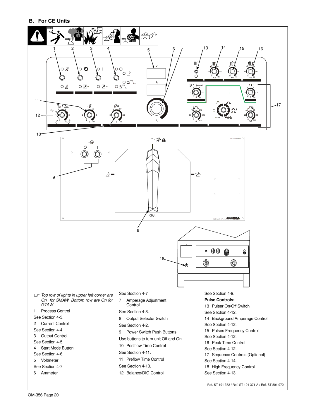
.Top row of lights in upper left corner are On for SMAW. Bottom row are On for GTAW.
1Process Control See Section
2Current Control See Section
3Output Control
See Section
4 Start Mode Button
See Section
5Voltmeter See Section
6Ammeter
See Section
7Amperage Adjustment Control
See Section
8Output Selector Switch See Section
9Power Switch Push Buttons
Use buttons to turn unit Off and On.
10Postflow Time Control See Section
11Preflow Time Control
See Section
12 Balance/DIG Control
See Section
Pulse Controls:
13Pulser On/Off Switch See Section
14Background Amperage Control See Section
15Pulses Frequency Control
See Section
16Peak Time Control See Section
17Sequence Controls (Optional) See Section
18High Frequency Control
See Section
Ref.
