S E C T I O N 2
Mounting, Wiring, and Setup
• • • • • • • • • • • • • • • • • • • • • • • • • • • • • • • • • • • • • • • • • • • • • • • • •
In This Section
♦ Setup Considerations | ♦ Wiring and Setup of Optiflex |
| |
♦ Mounting Optiflex |
|
• • • • • • • • • • • • • • • • • • • • • • • • • • • • • • • • • • • • • • • • • • • • • • • • •
Setup Considerations
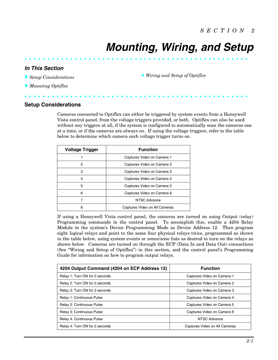
Cameras connected to Optiflex can either be triggered by system events from a Honeywell Vista control panel, from the voltage triggers provided, or both. Optiflex can also be used without any triggers at all, if the system is configured to automatically scan the cameras one at a time, or if the cameras are always on. If using the voltage triggers, refer to the table below to determine which camera each voltage trigger turns on.
Voltage Trigger | Function |
|
|
1 | Captures Video on Camera 1 |
|
|
2 | Captures Video on Camera 2 |
|
|
3 | Captures Video on Camera 3 |
|
|
4 | Captures Video on Camera 4 |
|
|
5 | Captures Video on Camera 5 |
|
|
6 | Captures Video on Camera 6 |
|
|
7 | NTSC Advance |
|
|
8 | Captures Video on All Cameras |
|
|
If using a Honeywell Vista control panel, the cameras are turned on using Output (relay) Programming commands in the control panel. To accomplish this, enable a 4204 Relay Module in the system’s Device Programming Mode as Device Address 12. Then program eight logical relays and point to the same four physical relays twice, programmed as shown in the table below, using system events or zones/zone lists as desired to turn on the relays as shown below. Cameras are turned on through the ECP (Data In and Data Out) connections (See “Wiring and Setup of Optiflex”) in this section, and the control panel’s Programming Guide for information on how to program output relays.
4204 Output Command (4204 on ECP Address 12) | Function |
|
|
Relay 1: Turn ON for 2 seconds | Captures Video on Camera 1 |
|
|
Relay 2: Turn ON for 2 seconds | Captures Video on Camera 2 |
|
|
Relay 3: Turn ON for 2 seconds | Captures Video on Camera 3 |
|
|
Relay 1: Continuous Pulse | Captures Video on Camera 4 |
|
|
Relay 2: Continuous Pulse | Captures Video on Camera 5 |
|
|
Relay 3: Continuous Pulse | Captures Video on Camera 6 |
|
|
Relay 4: Continuous Pulse | NTSC Advance |
|
|
Relay 4: Turn ON for 2 seconds | Captures Video on All Cameras |
|
|
