Optiflex Installation and Setup Guide
Optiflex Typical System Block Diagram
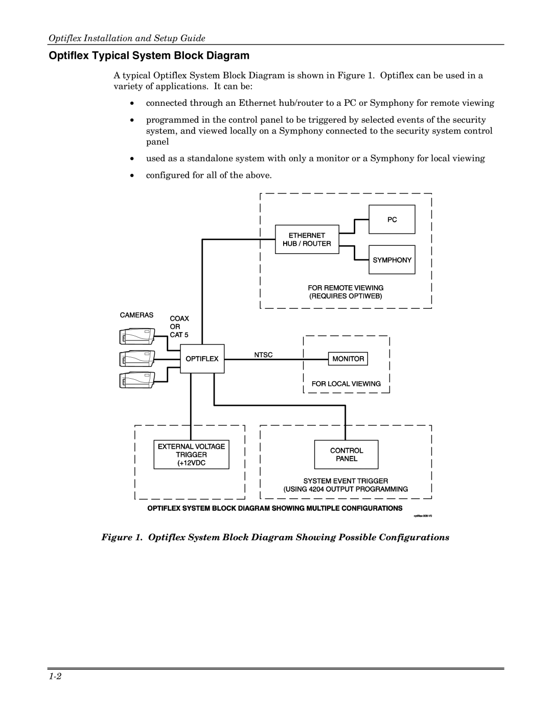
A typical Optiflex System Block Diagram is shown in Figure 1. Optiflex can be used in a variety of applications. It can be:
•connected through an Ethernet hub/router to a PC or Symphony for remote viewing
•programmed in the control panel to be triggered by selected events of the security system, and viewed locally on a Symphony connected to the security system control panel
•used as a standalone system with only a monitor or a Symphony for local viewing
•configured for all of the above.