Section 2: Mounting and Wiring
Wiring and Setup of Optiflex
Before wiring Optiflex, make sure power is turned off and review the important notes below.
1.Use a Listed Class 2 power supply suited for the application (see Section 5: Specifications).
2.Panel triggered UL Installations: Optiflex may be connected as a supplemental device to listed fire and/or burglar alarm control panels that support the 4204 relay module except as noted below.
UL | • In UL installations, Optiflex may be connected to panels that have ground fault |
detection only if the local authority having jurisdiction allows the ground fault | |
detection feature to be disabled. |
•In
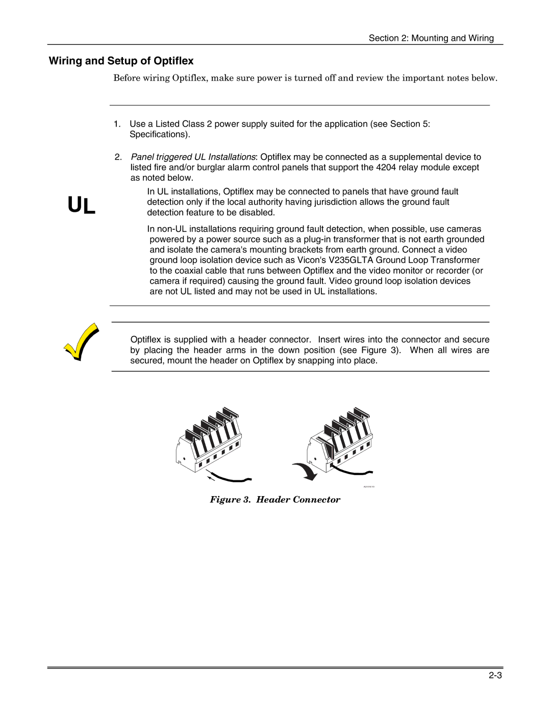
Optiflex is supplied with a header connector. Insert wires into the connector and secure by placing the header arms in the down position (see Figure 3). When all wires are secured, mount the header on Optiflex by snapping into place.