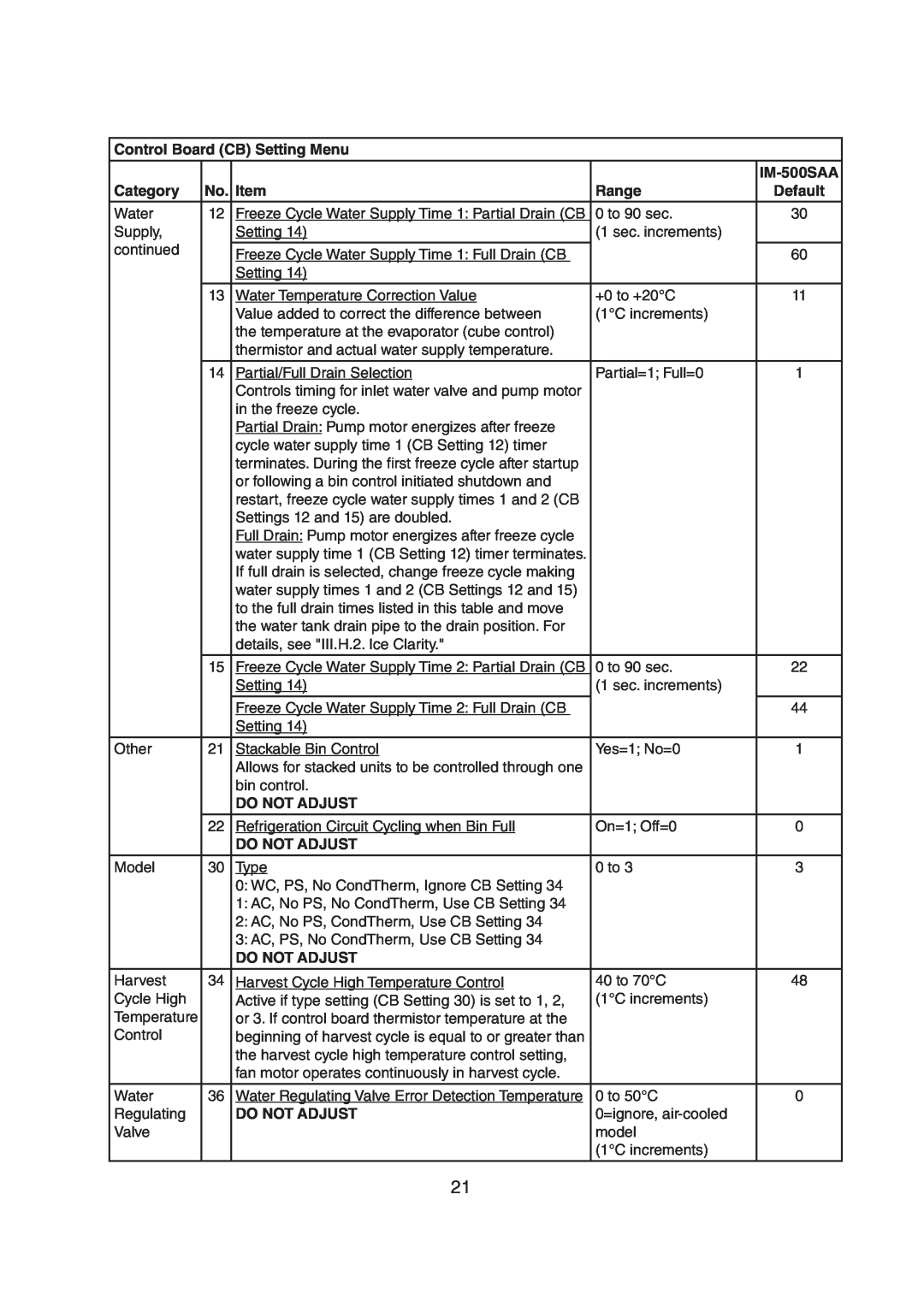
Control Board (CB) Setting Menu
|
|
|
| |
Category | No. | Item | Range | Default |
Water | 12 | Freeze Cycle Water Supply Time 1: Partial Drain (CB | 0 to 90 sec. | 30 |
Supply, |
| Setting 14) | (1 sec. increments) |
|
continued |
| Freeze Cycle Water Supply Time 1: Full Drain (CB |
| 60 |
|
|
| ||
|
| Setting 14) |
|
|
|
|
|
|
|
| 13 | Water Temperature Correction Value | +0 to +20°C | 11 |
|
| Value added to correct the difference between | (1°C increments) |
|
|
| the temperature at the evaporator (cube control) |
|
|
|
| thermistor and actual water supply temperature. |
|
|
|
|
|
|
|
| 14 | Partial/Full Drain Selection | Partial=1; Full=0 | 1 |
|
| Controls timing for inlet water valve and pump motor |
|
|
|
| in the freeze cycle. |
|
|
|
| Partial Drain: Pump motor energizes after freeze |
|
|
|
| cycle water supply time 1 (CB Setting 12) timer |
|
|
|
| terminates. During the first freeze cycle after startup |
|
|
|
| or following a bin control initiated shutdown and |
|
|
|
| restart, freeze cycle water supply times 1 and 2 (CB |
|
|
|
| Settings 12 and 15) are doubled. |
|
|
|
| Full Drain: Pump motor energizes after freeze cycle |
|
|
|
| water supply time 1 (CB Setting 12) timer terminates. |
|
|
|
| If full drain is selected, change freeze cycle making |
|
|
|
| water supply times 1 and 2 (CB Settings 12 and 15) |
|
|
|
| to the full drain times listed in this table and move |
|
|
|
| the water tank drain pipe to the drain position. For |
|
|
|
| details, see "III.H.2. Ice Clarity." |
|
|
|
|
|
|
|
| 15 | Freeze Cycle Water Supply Time 2: Partial Drain (CB | 0 to 90 sec. | 22 |
|
| Setting 14) | (1 sec. increments) |
|
|
|
|
|
|
|
| Freeze Cycle Water Supply Time 2: Full Drain (CB |
| 44 |
|
| Setting 14) |
|
|
Other | 21 | Stackable Bin Control | Yes=1; No=0 | 1 |
|
| Allows for stacked units to be controlled through one |
|
|
|
| bin control. |
|
|
|
| DO NOT ADJUST |
|
|
|
|
|
|
|
| 22 | Refrigeration Circuit Cycling when Bin Full | On=1; Off=0 | 0 |
|
| DO NOT ADJUST |
|
|
|
|
|
|
|
Model | 30 | Type | 0 to 3 | 3 |
|
| 0: WC, PS, No CondTherm, Ignore CB Setting 34 |
|
|
|
| 1: AC, No PS, No CondTherm, Use CB Setting 34 |
|
|
|
| 2: AC, No PS, CondTherm, Use CB Setting 34 |
|
|
|
| 3: AC, PS, No CondTherm, Use CB Setting 34 |
|
|
|
| DO NOT ADJUST |
|
|
Harvest | 34 | Harvest Cycle High Temperature Control | 40 to 70°C | 48 |
Cycle High |
| Active if type setting (CB Setting 30) is set to 1, 2, | (1°C increments) |
|
Temperature |
| or 3. If control board thermistor temperature at the |
|
|
Control |
| beginning of harvest cycle is equal to or greater than |
|
|
|
| the harvest cycle high temperature control setting, |
|
|
|
| fan motor operates continuously in harvest cycle. |
|
|
Water | 36 | Water Regulating Valve Error Detection Temperature | 0 to 50°C | 0 |
Regulating |
| DO NOT ADJUST | 0=ignore, |
|
Valve |
|
| model |
|
|
|
| (1°C increments) |
|
|
|
|
|
|
21
