II. Sequence of Operation and Service Diagnosis
A. Sequence of Operation Flow Chart
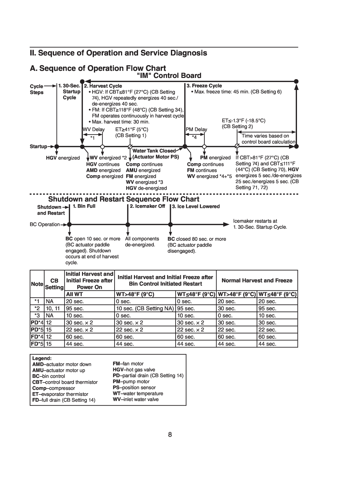
"IM" Control Board
Cycle |
| 1. | 2. Harvest Cycle | 3. Freeze Cycle |
| ||||
Steps |
| Startup | • HGV: If CBT≤81°F (27°C) (CB Setting | • Max. freeze time: 45 min. (CB Setting 6) |
|
| Cycle | 74), HGV repeatedly energizes 40 sec./ |
|
|
|
|
|
•FM: If CBT≥118°F (48°C) (CB Setting 34), FM operates continuously in harvest cycle
|
|
|
|
| • Max. harvest time: 30 min. |
|
|
|
| |||||||||||
|
|
|
| WV Delay | ET≥41°F (5°C) | PM Delay | (CB Setting 2) | |||||||||||||
|
|
|
|
|
|
|
|
|
| |||||||||||
|
|
|
|
|
|
|
| (CB Setting 1) |
|
|
|
|
|
|
| Time varies based on |
| |||
|
|
|
| *1 |
|
| *4 |
|
|
| ||||||||||
Startup |
|
|
|
|
|
|
|
|
|
|
|
|
| control board calculation | ||||||
|
|
|
|
|
|
|
|
|
|
|
|
|
|
|
|
| ||||
|
|
|
|
|
|
|
|
|
|
|
|
|
|
|
|
|
|
|
| |
|
|
|
|
|
|
|
| Water Tank Closed |
|
|
|
|
|
|
|
|
|
| ||
|
|
|
|
|
|
|
|
|
|
|
|
|
|
|
|
|
|
|
| |
HGV energized |
| WV energized *2 (Actuator Motor PS) |
| PM energized | If CBT>81°F (27°C) (CB | |||||||||||||||
|
|
|
|
| HGV continues | Comp continues | Comp continues | Setting 74) and CBT≤111°F | ||||||||||||
|
|
|
|
| AMD energized | AMU energized | FM continues |
| (44°C) (CB Setting 70), HGV | |||||||||||
|
|
|
|
| Comp energized | FM energized | WV energized *4+*5 | energizes 5 | ||||||||||||
|
|
|
|
|
|
|
|
| WV energized *3 |
|
|
|
|
| 25 sec./energizes 5 sec. (CB | |||||
|
|
|
|
|
|
|
|
| HGV |
|
|
|
|
| Setting 71, 72) | |||||
Shutdown and Restart Sequence Flow Chart
Shutdown |
| 1. Bin Full | 2. Icemaker Off 3. Ice Level Lowered |
| |||
and Restart |
|
| |
BC Operation |
|
|
|
|
|
|
| BC open 10 sec. or more | All components | BC closed 80 sec. or more | |||
|
| |||||
|
| (BC actuator paddle | (BC actuator paddle | |||
|
| engaged). Shutdown |
| disengaged). | ||
|
| occurs at end of harvest |
|
|
| |
|
| cycle. |
|
|
| |
Icemaker restarts at
1.
|
|
| Initial Harvest and | Initial Harvest and Initial Freeze after |
|
| |||
| CB |
| Initial Freeze after |
| Normal Harvest and Freeze | ||||
Note | Setting |
| Power On |
| Bin Control Initiated Restart |
|
| ||
|
|
| All WT |
| WT>48°F (9°C) | WT≤48°F (9°C) | WT>48°F (9°C) | WT≤48°F (9°C) | |
*1 | NA |
| 20 sec. |
| 0 sec. | 0 sec. | 20 sec. | 20 sec. | |
*2 | 10, 11 |
| 95 sec. |
| 10 sec. (CB Setting NA) | 95 sec. | 30 sec. | 95 sec. | |
*3 | NA |
| 10 sec. |
| 0 sec. | 10 sec. | 0 sec. | 10 sec. | |
PD*4 | 12 |
| 30 sec. × 2 |
| 30 sec. × 2 | 30 sec. × 2 | 30 sec. | 30 sec. | |
PD*5 | 15 |
| 22 sec. × 2 |
| 22 sec. × 2 | 22 sec. × 2 | 22 sec. | 22 sec. | |
FD*4 | 12 |
| 60 sec. |
| 60 sec. | 60 sec. | 60 sec. | 60 sec. | |
FD*5 | 15 |
| 44 sec. |
| 44 sec. | 44 sec. | 44 sec. | 44 sec. | |
|
|
|
|
|
|
|
|
|
|
Legend: |
|
|
|
|
| ||||
|
|
|
| ||||||
|
|
|
| ||||||
|
|
|
| ||||||
|
|
|
| ||||||
|
|
|
| ||||||
|
|
|
| ||||||
|
|
|
| ||||||
|
|
|
|
|
|
|
|
|
|
8