Cable Pinouts |
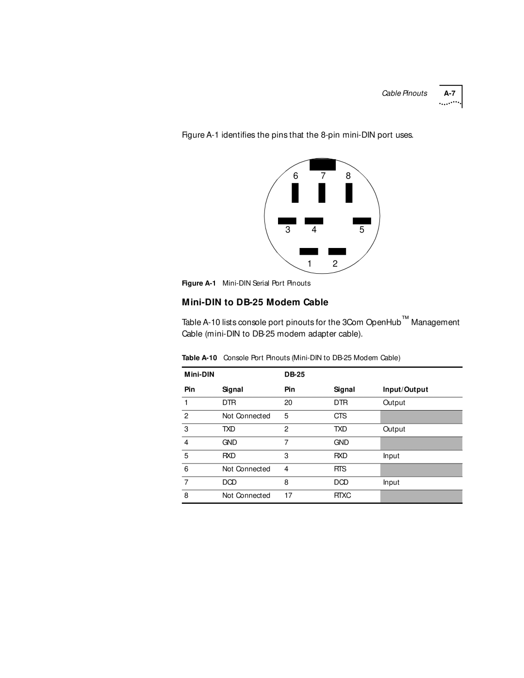
Figure A-1 identifies the pins that the 8-pin mini-DIN port uses.
6 7 8
3 | 4 | 5 |
1 2
Figure A-1 Mini-DIN Serial Port Pinouts
Table
Table
|
|
| ||
Pin | Signal | Pin | Signal | Input/Output |
|
|
|
|
|
1 | DTR | 20 | DTR | Output |
|
|
|
|
|
2 | Not Connected | 5 | CTS |
|
|
|
|
|
|
3 | TXD | 2 | TXD | Output |
|
|
|
|
|
4 | GND | 7 | GND |
|
|
|
|
|
|
5 | RXD | 3 | RXD | Input |
|
|
|
|
|
6 | Not Connected | 4 | RTS |
|
|
|
|
|
|
7 | DCD | 8 | DCD | Input |
|
|
|
|
|
8 | Not Connected | 17 | RTXC |
|
|
|
|
|
|