Configuring DIP Switches |
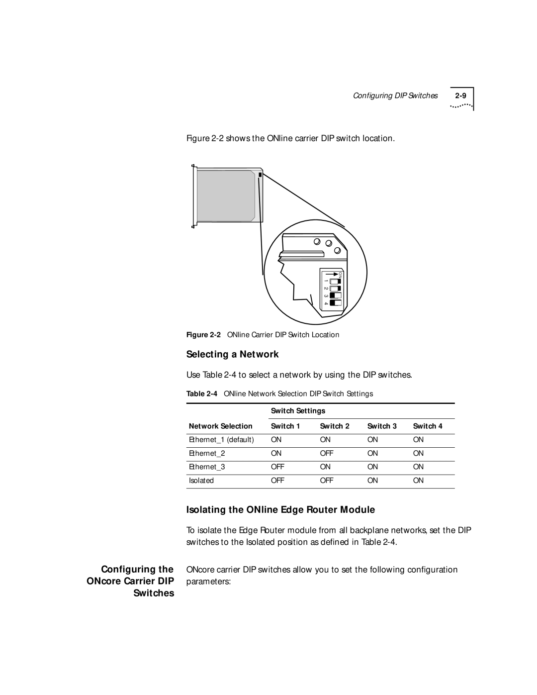
Figure 2-2 shows the ONline carrier DIP switch location.
![]() O N 1 2 3 4
O N 1 2 3 4![]()
![]()
![]()
![]()
Figure 2-2 ONline Carrier DIP Switch Location
Selecting a Network
Use Table
| Table |
|
| |||
|
|
|
|
|
| |
|
| Switch Settings |
|
|
| |
|
|
|
|
|
|
|
| Network Selection | Switch 1 | Switch 2 | Switch 3 | Switch 4 | |
|
|
|
|
|
|
|
| Ethernet_1 (default) | ON | ON | ON | ON | |
|
|
|
|
|
|
|
| Ethernet_2 | ON | OFF | ON | ON | |
|
|
|
|
|
|
|
| Ethernet_3 | OFF | ON | ON | ON | |
|
|
|
|
|
|
|
| Isolated | OFF | OFF | ON | ON | |
|
|
|
| |||
| Isolating the ONline Edge Router Module |
|
| |||
| To isolate the Edge Router module from all backplane networks, set the DIP | |||||
| switches to the Isolated position as defined in Table |
|
| |||
Configuring the | ONcore carrier DIP switches allow you to set the following configuration | |||||
ONcore Carrier DIP | parameters: |
|
|
|
|
|
Switches |
|
|
|
|
|
|
