Chapter 4 - Using the Data Processing Feature | Data Processing Feature |
Using the Dipole and Isotropic Link Calculator-
Use the ideal dipole to simulate an entire link measurement set. Then you may perform calculator operations that you can use to normalize and compare your measurements to.
The calculations are for any dipole length over any frequency range for any rotation sequence. Be advised the calculation can become enormous if you
choose a very long or very short lengths compared to a wavelength. The Si and Ci sin(x)/x and cos(x)/x intergrals are numerically calculated.
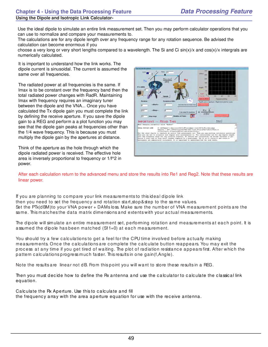
It is important to understand how the link works. The dipole current is sinusoidal. The current is assumed the same over all frequencies.
The radiated power at all frequencies is the same. If Imax is to be constant over the frequency band then the total radiated power changes with RadR. Maintaining Imax with frequency requires an imaginary tuner between the dipole and the VNA... Once you have calculated the Tx dipole gain you must complete the link by defining the receive aperture. If you save the dipole gain to a REG and perform a a plot function you may see that the dipole gain peaks at frequencies other than the 1/4 wave frequency. This is because you must multiply the dipole gain by the apertures at distance.
Think of the aperture as the hole through which the dipole radiated power is received. The effective hole area is inversely proportional to frequency or 1/f^2 in power.
After each calculation return to the advanced menu and store the results into Re1 and Reg2. Note that these results are linear power.
If you are planning to compare your link measurements to this ideal dipole link
then you need to set the frequency and rotation start,stop&step to the same values.
Set the PTx(dBM)to your VNA power + DAMs loss. Make sure the number of VNA measurement points are the same. This matches the data matrix dimensions and extents with your actual measurements.
The dipole will simulate an entire measurement set, performing rotation and measurements at each point. It is assumed the dipole has been matched (S11=0) at each measurement.
You should try a few calculations to get a feel for the CPU time involved before actually making measurements. Once the calculations are complete the calculate button reappears. You may exit the process at any time if you get tired of waiting. The plot of radiation resistance appears first. After which the pattern calculations progress much faster. This results in one gain(f,Angle).
Note the results are linear not dB. From this point you will want to store these results in a REG.
Then you must decide how to define the Rx antenna and use the calculator to calculate the classical link equation.
Calculate the Rx Aperture. Use this to calculate and fill
the frequency array with the area aperture equation for use with the receive antenna.
49