Removal and replacement procedures
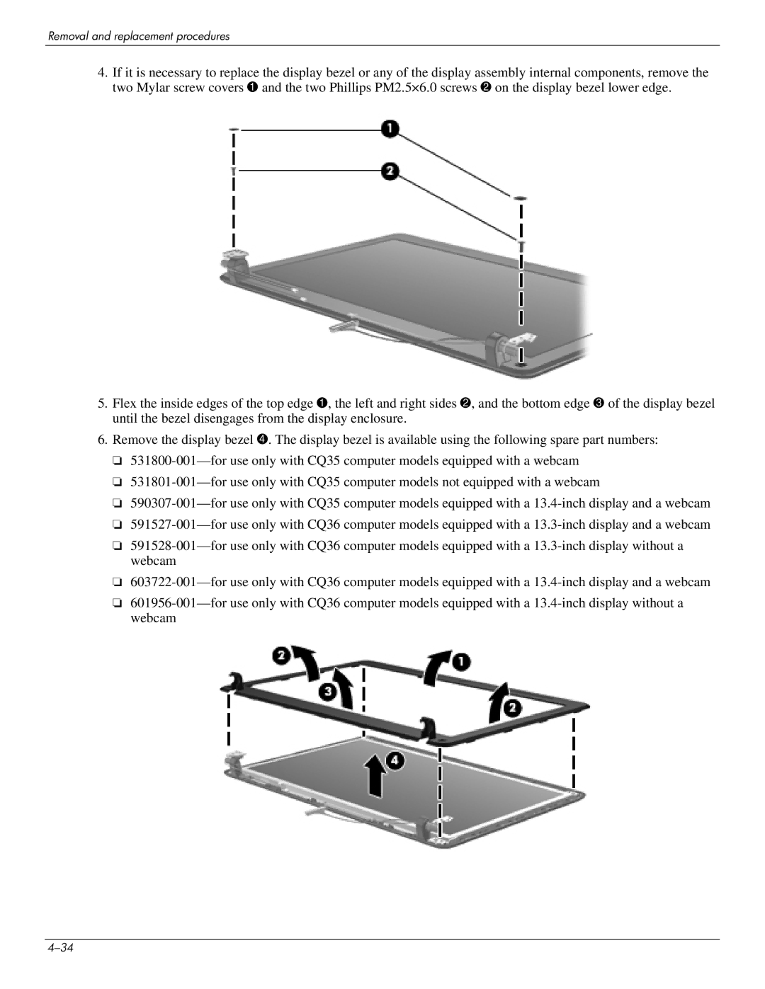
4.If it is necessary to replace the display bezel or any of the display assembly internal components, remove the two Mylar screw covers 1 and the two Phillips PM2.5×6.0 screws 2 on the display bezel lower edge.
5.Flex the inside edges of the top edge 1, the left and right sides 2, and the bottom edge 3 of the display bezel until the bezel disengages from the display enclosure.
6.Remove the display bezel 4. The display bezel is available using the following spare part numbers:
❏531800-001—for use only with CQ35 computer models equipped with a webcam
❏531801-001—for use only with CQ35 computer models not equipped with a webcam
❏590307-001—for use only with CQ35 computer models equipped with a 13.4-inch display and a webcam
❏591527-001—for use only with CQ36 computer models equipped with a 13.3-inch display and a webcam
❏591528-001—for use only with CQ36 computer models equipped with a 13.3-inch display without a webcam
❏603722-001—for use only with CQ36 computer models equipped with a 13.4-inch display and a webcam
❏601956-001—for use only with CQ36 computer models equipped with a 13.4-inch display without a webcam

