9.If it is necessary to replace any of the display assembly internal components, remove the following screw covers and screws. The display rubber screw covers are included in the Display Rubber Kit, spare part number
(1)Two Mylar screw covers on the display bezel bottom edge
(2)Two Phillips PM2.5×5.0 screws
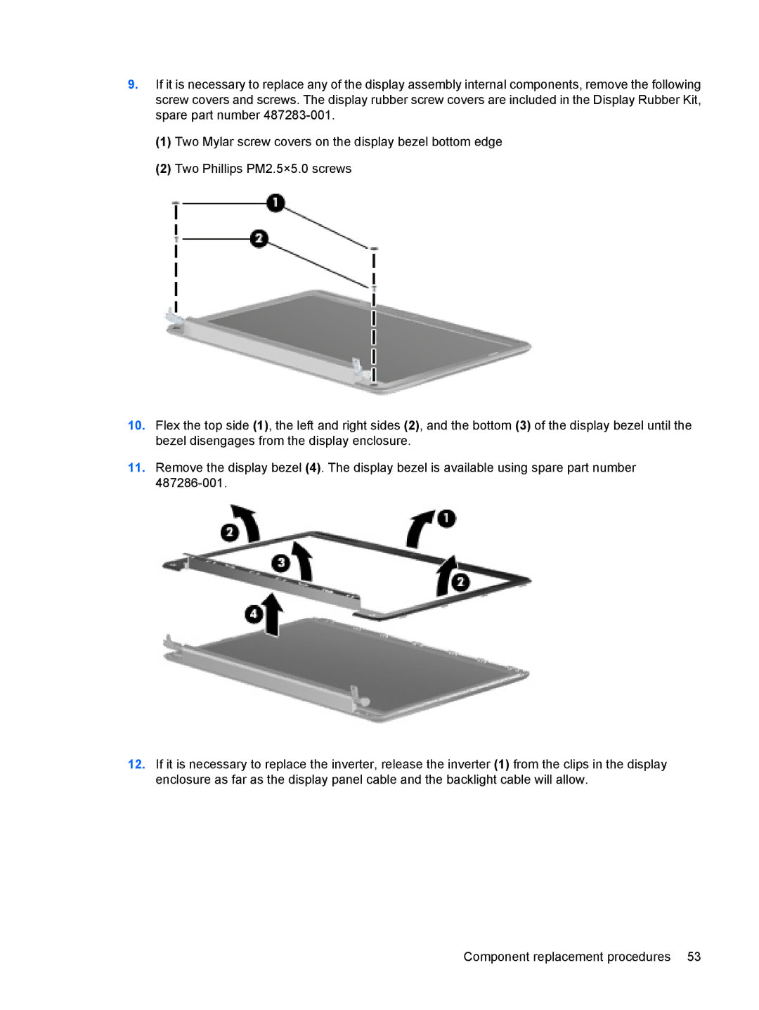
10.Flex the top side (1), the left and right sides (2), and the bottom (3) of the display bezel until the bezel disengages from the display enclosure.
11.Remove the display bezel (4). The display bezel is available using spare part number
12.If it is necessary to replace the inverter, release the inverter (1) from the clips in the display enclosure as far as the display panel cable and the backlight cable will allow.
Component replacement procedures 53