Maintenance and Service Guide
Page
Contents
Illustrated Parts Catalog
Specifications
Contents
Product Description
Features
Product Description
Resetting the Notebook
Power Management
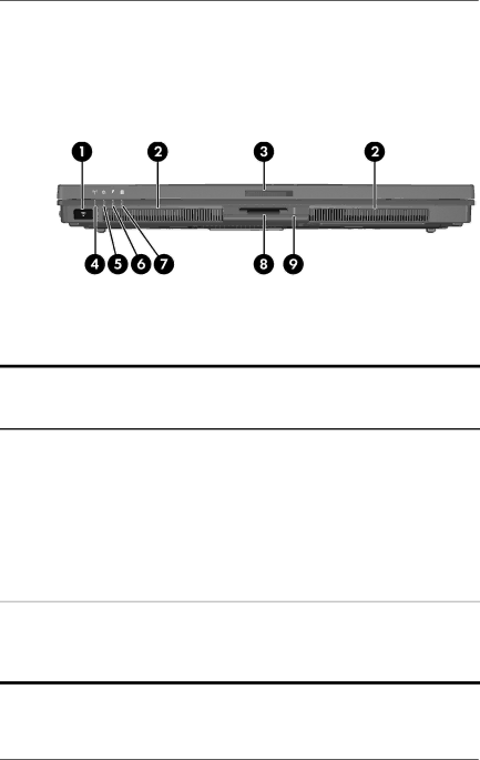
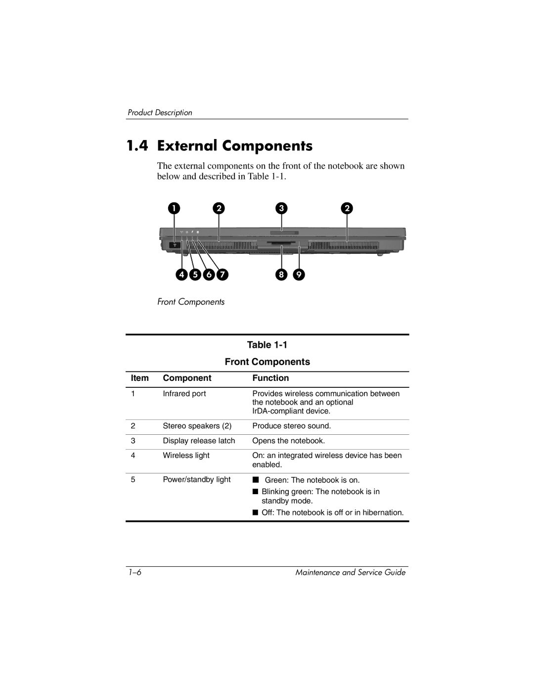
External Components
Front Components
Front Components
Right-Side Components
Right-Side Components
Left-Side Components
Left-Side Components
Rear Panel Components
Rear Panel Components
Standard Keyboard Components
Standard Keyboard Components
Caps lock key
Fn key
Num lock key
Top Components, Part
Top Components, Part
Top Components, Part
Top Components, Part
Bottom Components
Bottom Components
Design Overview
Troubleshooting
Computer Setup
Accessing Computer Setup
File Menu
Select To Do This
Selecting from the Security Menu
Security Menu
Selecting from the Tools Menu
Tools Menu
Selecting from the Advanced Menu
Advanced Menu
Troubleshooting Flowcharts
Troubleshooting Flowcharts Overview
Flowchart 2.14-No OS Loading, Optical Drive
Flowchart 2.1-Initial Troubleshooting
Flowchart 2.2-No Power, Part
Flowchart 2.2-No Power, Part
Flowchart 2.3-No Power, Part
Flowchart 2.4-No Power, Part
External
Flowchart 2.5-No Power, Part
Flowchart 2.6-No Video, Part
Flowchart 2.7-No Video, Part
Flowchart 2.6-No Video, Part
Flowchart 2.8-Nonfunctioning Docking Device if applicable
Reseat power Cord in docking Device Power outlet
Flowchart 2.9-No Operating System OS Loading
Flowchart 2.10-No OS Loading, Hard Drive, Part
OS not Loading from Hard drive
Flowchart 2.11-No OS Loading, Hard Drive, Part
Flowchart 2.12-No OS Loading Hard Drive, Part
Flowchart 2.12-No OS Loading, Hard Drive, Part
Flowchart 2.11-No OS Loading Hard Drive, Part
Flowchart 2.13-No OS Loading, Diskette Drive
Diskette drive
Flowchart 2.14-No OS Loading, Optical Drive
Flowchart 2.15-No Audio, Part
Flowchart No Audio Part
Flowchart 2.16-No Audio, Part
Flowchart 2.15-No Audio, Part
Flowchart 2.17-Nonfunctioning Device
Cmos
Flowchart 2.18-Nonfunctioning Keyboard
Flowchart 2.19-Nonfunctioning Pointing Device
Flowchart 2.20-No Network/Modem Connection
Software Update Recovery
Software Updates
Accessing Computer Information
Obtaining the Support Software Disc
Software Updates HP Web Site
Downloading a Bios Update
Installing a Bios Update
Recovering the Bios
Software Update and Recovery
Illustrated Parts Catalog
Serial Number Location
Illustrated Parts Catalog
Switch cover
Spare Parts Notebook Major Components
LED board
Keyboards
Illustrated Parts Catalog
Serial connector module
Miscellaneous Plastics Kit
Modem board
Memory modules 533-MHz DDR2
Illustrated Parts Catalog
Battery packs
Broadcomm Bluetooth wireless board includes
Spare Part
Mini PCI communications cards
Miscellaneous Plastics Kit
Miscellaneous Plastics Kit Spare Part Number
Miscellaneous Cable Kit
Miscellaneous Cable Kit Spare Part Number
Mass Storage Devices
Mass Storage Devices Spare Part Number Information
Miscellaneous Not Illustrated
Miscellaneous Not Illustrated Spare Part Information
Description Number
Appendix C, Screw Listing, for more information on
Sequential Part Number Listing
Sequential Part Number Listing
Sequential Part Number Listing
Sequential Part Number Listing
Sequential Part Number Listing
Removal and Replacement Preliminaries
Tools Required
Service Considerations
Plastic Parts
Preventing Damage to Removable Drives
Preventing Electrostatic Damage
Packaging and Transporting Precautions
Workstation Precautions
Grounding Equipment and Methods
Removal and Replacement Preliminaries
Typical Electrostatic Voltage Levels
Static-Shielding Materials
Relative Humidity Event 10% 40% 55%
Material Use Voltage Protection Level
Removal and Replacement Procedures
Disassembly Sequence Chart
Disassembly Sequence Chart
Serial Number
# of Screws Removed
Disassembly Sequence Chart
Preparing the Notebook for Disassembly
Battery Pack Spare Part Number Information
Reverse the above procedure to install the battery pack
Hard Drive
Hard Drive Spare Part Number Information
Removing the Hard Drive
Removing the Hard Drive Frame and Connector
Replacing the Notebook Feet
Bluetooth Board
Bluetooth Board Spare Part Number Information
Reverse the above procedure to install a Bluetooth board
External Memory Module
Memory Module Spare Part Number Information
Reverse the above procedure to install a memory module
Mini PCI Communications Card
Mini PCI Communications Card Spare Part Number Information
Removing a Mini PCI Communications Card
Optical Drive
Optical Drive Spare Part Number Information
Reverse the above procedure to install an optical drive
Keyboard
Keyboard Spare Part Number Information
Releasing the Keyboard Latches
Releasing the Keyboard
Disconnecting the Keyboard Cable
Switch Cover
Switch Cover Spare Part Number Information
Reverse the above procedure to install the switch cover
LED Board
LED Board Spare Part Number Information
Reverse the above procedure to install the LED board
13 Fan
Fan Spare Part Number Information
Heat Sink
Heat Sink Spare Part Number Information
Removing the Heat Sink
Reverse the above procedure to install the heat sink
Processor
Processor Spare Part Number Information
Reverse the above procedure to install the processor
Internal Memory Module
Reverse the above procedure to install a memory module
RTC Battery
Display Assembly
Display Assembly Spare Part Number Information
Removal and Replacement Procedures
Reverse the above procedure to install the display assembly
Top Cover
Top Cover Spare Part Number Information
Removing the Top Cover Screws, Part
Removing the Top Cover Screws, Part
Releasing the Top Cover
Speaker
Speaker Spare Part Number Information
Reverse the above procedure to install the speaker
Modem Board
Modem Board Spare Part Number Information
Reverse the above procedure to install the modem board
Digital Media Board
Digital Media Board Spare Part Number Information
Removing the Digital Media Board
23 USB/Audio Board
USB/Audio Board Spare Part Number Information
Reverse the above procedure to install the USB/audio board
System Board
System Board Spare Part Number Information
Fan Section
Removing the System Board Screws and Screw Locks
Removing the System Board
Reverse the above procedures to install the system board
Serial Connector Module
Serial Connector Module Spare Part Number Information
Removing the Serial Connector Module
Dimensions Metric
Weight
Input Power
Temperature
Maximum altitude unpressurized
Shock
Random Vibration
Inch, SXGA+WVA, TFT Display
Inch, XGA, TFT Display
Height 28.5 cm 11.2 Width 21.3 cm Diagonal 35.8 cm 14.1
Hard Drives
Primary 6-cell, Li-Ion Battery Pack
Energy
DVD-ROM Drive
DVD/CD-RW Combo Drive
Applicable disc Read Write
Cache buffer Data transfer rate
DVD±RW and CD-RW Combo Drive
Random 175 ms 230 ms Full stroke 285 ms 335 ms
System DMA
Hardware DMA System Function
System Interrupts
IRQ
System I/O Addresses
Address hex
RTC/CMOS
VGA
System Memory Map
Size Memory Address System Function
Pin Signal
Table A-1 Audio-Out Headphone
Table A-2 Audio-In Microphone
Table A-3 Universal Serial Bus
Table A-4 Serial
Table A-5 Parallel Port
Table A-6 Pin S-Video-Out
Table A-7 External Monitor
Table A-8 RJ-11 Modem
Table A-9 RJ-45 Network
Power Cord Set Requirements
Conductor Power Cord Set
General Requirements
Conductor Power Cord Set Requirements
Country-Specific Requirements
Country/Region Accredited Agency Applicable Note Number
Kema
Screw Listing
Color Qty Length Thread Width Black Where used
Table C-1 Phillips PM2.0×4.0 Screw
Head
Color Qty Length Thread Width Silver 13.0 mm Where used
Color Qty Length Thread Width Silver Head Black Where used
Table C-4 Torx T8M2.0×9.0 Screw
Head Color Qty. Length Thread Width
Table C-4 Torx T8M2.0×9.0 Screw
Table C-4 Torx T8M2.0×9.0 Screw
Table C-4 Torx T8M2.0×9.0 Screw
Table C-4 Torx T8M2.0×9.0 Screw
Table C-5 Torx T8M2.0×2.0 Screw
Color Qty Length Thread Width Silver Where used
Table C-6 Phillips PM1.5×4.0 Screw
Table C-7 Phillips PM2.0×7.0 Screw
Table C-8 Phillips PM2.0×8.0 Shoulder Screw
Table C-9 Phillips PM2.0×3.0 Screw
Table C-10 Torx T8M2.0×4.0 Screw
Torx T8M2.0×4.0 Screw Location
Table C-10 Torx T8M2.0×4.0 Screw
Table C-11 Hex Socket HM5.0×9.0 Screw Lock
Head
Index
Index
Index-3
Index-4
Index-5
Index-6
Index-7