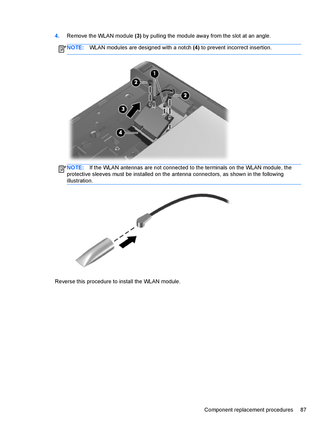
4.Remove the WLAN module (3) by pulling the module away from the slot at an angle.
![]() NOTE: WLAN modules are designed with a notch (4) to prevent incorrect insertion.
NOTE: WLAN modules are designed with a notch (4) to prevent incorrect insertion.
![]()
![]()
![]()
![]() NOTE: If the WLAN antennas are not connected to the terminals on the WLAN module, the protective sleeves must be installed on the antenna connectors, as shown in the following illustration.
NOTE: If the WLAN antennas are not connected to the terminals on the WLAN module, the protective sleeves must be installed on the antenna connectors, as shown in the following illustration.
Reverse this procedure to install the WLAN module.