Replacing the Front Bezel
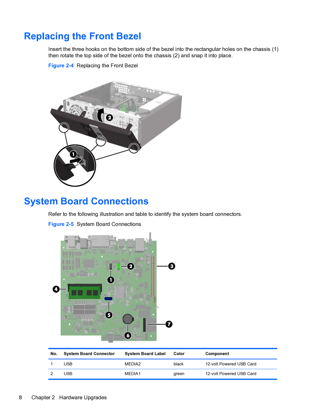
Insert the three hooks on the bottom side of the bezel into the rectangular holes on the chassis (1) then rotate the top side of the bezel onto the chassis (2) and snap it into place.
Figure 2-4 Replacing the Front Bezel
System Board Connections
Refer to the following illustration and table to identify the system board connectors.
Figure 2-5 System Board Connections
No. | System Board Connector | System Board Label | Color | Component |
|
|
|
|
|
1 | USB | MEDIA2 | black | |
|
|
|
|
|
2 | USB | MEDIA1 | green | |
|
|
|
|
|
8 Chapter 2 Hardware Upgrades
