15 | Rotary encoder | When this is rotated while the MENU key is ON, menus or programs can | ||||
| be selected. | |||||
|
|
|
|
| ||
16 | LOCK switch 1 | This is the operation lock switch. When it is set to ON, none of the | ||||
| panel keys can be operated. | |||||
|
|
|
|
| ||
17 | LOCK switch 2 | This is the picture ON switch. It enables the rear panel images to be set | ||||
| to ON or OFF. | |||||
|
|
|
|
| ||
|
|
|
|
|
| |
|
|
|
|
|
| |
|
|
|
| Always remember to handle the CF cards with great care. When inserting or |
| |
|
|
|
| ejecting a card, follow the instructions in section 3.2.3 "How to insert the CF |
| |
|
|
|
| cards" or section 3.2.4 "How to eject the CF cards." |
| |
|
|
|
| Failing to take the steps in the prescribed sequence may cause the CF card |
| |
|
| CAUTION | ||||
|
|
|
| data to be destroyed. In such a case, the CF card will no longer be |
| |
|
|
|
| recognized even when it is |
| |
|
|
|
|
|
|
|
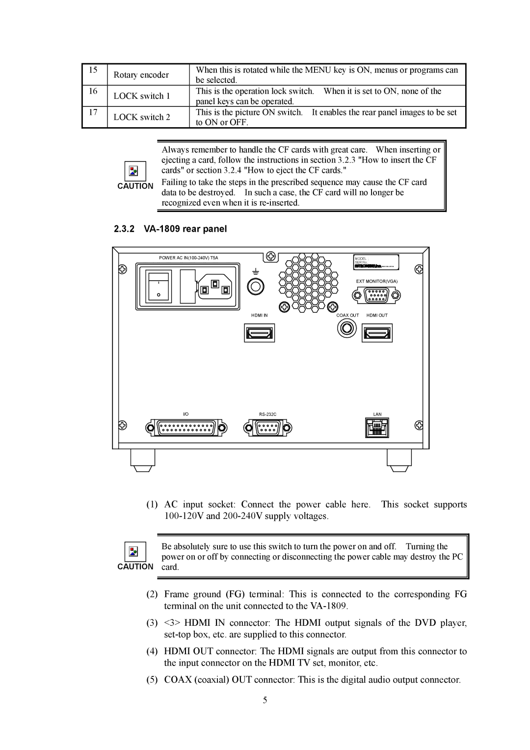
2.3.2VA-1809 rear panel
POWER AC |
| MODEL ; | |
|
| SER.No ; | |
|
|
| MADE IN JAPAN |
|
| EXT MONITOR(VGA) | |
| HDMI IN | COAX OUT | HDMI OUT |
I/O |
| LAN | |
(1)AC input socket: Connect the power cable here. This socket supports
Be absolutely sure to use this switch to turn the power on and off. Turning the power on or off by connecting or disconnecting the power cable may destroy the PC
CAUTION card.
(2)Frame ground (FG) terminal: This is connected to the corresponding FG terminal on the unit connected to the
(3)<3> HDMI IN connector: The HDMI output signals of the DVD player,
(4)HDMI OUT connector: The HDMI signals are output from this connector to the input connector on the HDMI TV set, monitor, etc.
(5)COAX (coaxial) OUT connector: This is the digital audio output connector.
5