Veritas Volume Manager Administrator’s Guide
Legal Notices
Page
Contents
Using vxdiskadd to place a disk under control of VxVM
VxVM root disk volume restrictions
Booting root volumes
Setting up a VxVM root disk and mirror
Taking a disk offline 118
119
133
136
167
185
207
Setting default values for vxassist 241
215
Displaying subdisk information 216
217
252
274
275
Moving volumes from a VM disk 290
288
289
290
Chapter Creating and administering volume sets
356
386
387
388
390
434
441
Setup tasks after installation 511
463
507
512
521 531
Understanding Veritas Volume Manager
Veritas Enterprise Administrator User’s Guide
VxVM and the operating system
How data is stored
How VxVM handles storage management
Physical objects-physical disks
Disk arrays
Multipathed disk arrays
Device discovery
Operating system
Enclosure-based naming
Fibre Channel hub or switch
Provide redundant loop access
C2t99d0
Virtual objects
Combining virtual objects in VxVM
Virtual objects in VxVM include the following
Connection between objects in VxVM
Disk groups
VM disks
Subdisks
Plexes
Volumes
How VxVM handles storage management
Disk01-01 vol06-01
Volume layouts in VxVM
Implementation of non-layered volumes
Implementation of layered volumes
Layout methods
Concatenation and spanning
Following sections describe each layout method
12 Example of concatenation Data Disk01-01
Example of spanning Data
+1 n+2
Striping RAID-0
Su1 Su2 Su3
Devname3
Devname2
Mirroring RAID-1
Striping plus mirroring mirrored-stripe or RAID-0+1
17 Mirrored-stripe volume laid out on six disks
Mirroring plus striping striped-mirror, RAID-1+0 or RAID-10
Column Mirror Striped plex
Mirror volumes
You need a full license to use this feature
RAID-5 striping with parity
Data Parity
Traditional RAID-5 arrays
Veritas Volume Manager RAID-5 arrays
22 Veritas Volume Manager RAID-5 array Stripe
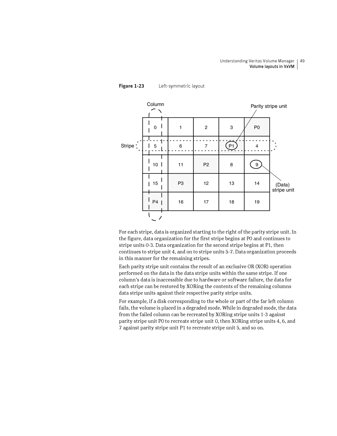
Left-symmetric layout
Understanding Veritas Volume Manager
RAID-5 logging
Layered volumes
Example of a striped-mirror layered volume
Understanding Veritas Volume Manager
Online relayout
How online relayout works
Three columns of length 5L/3
Striped volume
Limitations of online relayout
Transformation characteristics
Transformations and volume length
Volume resynchronization
Dirty flags
Resynchronization process
Dirty region logging
Dirty region logs
Log subdisks and plexes
Sequential DRL
SmartSync recovery accelerator
Data volume configuration
Volume snapshots
Redo log volume configuration
Original
Comparison of snapshot features
Space than original Volume
Use on creation Requires less storage
FastResync
FastResync enhancements
Non-persistent FastResync
DCO volume versioning
Persistent FastResync
How non-persistent FastResync works with snapshots
Version 0 DCO volume layout
Version 20 DCO volume layout
Where the size of each map in bytes is
How persistent FastResync works with snapshots
DCO
FastResync
Effect of growing a volume on the FastResync map
FastResync limitations
Volume sets
Hot-relocation
Volume sets
Administering disks
Disk devices
Disk device naming in VxVM
Operating system-based naming
There are two different methods of naming disk devices
# vxdisk path egrep diskname
Private and public disk regions
Configures disk access records for them automatically
To boot the system.Typically, most disks on a system are
Configured as this disk type. However, it is not a suitable
Format for boot, root or swap disks, for mirrors or
Discovering and configuring newly added disk devices
Following command scans for the devices c1t1d0 and c2t2d0
Partial device discovery
Next example discovers fabric devices
Discovering disks and dynamically adding disk arrays
Disk categories
For more information, see the vxdisk1M manual
Third-party driver coexistence
Adding support for a new disk array
Enabling discovery of new devices
Removing support for a disk array
Administering the Device Discovery Layer
Listing details of supported disk arrays
# vxddladm listsupport all
# vxddladm listsupport libname=libraryname.sl
Excluding support for a disk array library
Re-including support for an excluded disk array library
Listing excluded disk arrays
Listing supported disks in the Disks category
Adding unsupported disk arrays to the Disks category
Length=serialnolength policy=ap
# vxddladm addjbod vid=SEAGATE pid=ST318404LSUN18G
# vxdmpadm listenclosure all
# vxdisk list
Removing disks from the Disks category
Adding foreign devices
# vxddladm rmjbod vid=SEAGATE
Placing disks under VxVM control
See Migrating between DMP and HP-UX native multipathing on
Mode Format of output from VxVM command
Default
Changing the disk-naming scheme
Legacy
VxVM vxdmpadm Error V-5-1-10910 Invalid da-name
# vxdmpadm getlungroup dmpnodename=disk25
Restart the VxVM configuration demon
Regenerating persistent device names
This regenerates the persistent name database
Changing device naming for TPD-controlled enclosures
# vxdmpadm setattr enclosure enclosure tpdmode=nativepseudo
# vxdmpadm getsubpaths dmpnodename=enclosure-basedname
Persistent simple or nopriv disks in the boot disk group
# vxconfigd -kr reset
Installing and formatting disks
Persistent simple or nopriv disks in non-boot disk groups
Re-import the disk group using the following command
Displaying and changing default disk layout attributes
Add or initialize disks Menu VolumeManager/Disk/AddDisks
Adding a disk to VxVM
C3t0d0 c3t1d0 c3t2d0 c3t3d0
Continue operation? y,n,q,? default y y
Use default disk names for the disks? y,n,q,? default y
Exclude disks from hot-relocation use? y,n,q,? default n n
Add site tag to disks? y,n,q,? default n
Continue with operation? y,n,q,? default y y
Enter the desired format cdsdisk,hpdisk,q,? default cdsdisk
Enter desired private region length privlen,q,? default
Following disks
Using vxdiskadd to place a disk under control of VxVM
Add or initialize other disks? y,n,q,? default n
Reinitializing a disk
Vxdiskadm then proceeds to add the disks
Rootability
VxVM root disk volume restrictions
Root disk mirrors
Booting root volumes
Setting up a VxVM root disk and mirror
# /etc/vx/bin/vxcplvmroot -b c0t4d0
# /etc/vx/bin/vxcplvmroot -R 30 -v -b c0t4d0
# /etc/vx/bin/vxcplvmroot -m c1t1d0 -R 30 -v -b c0t4d0
Creating an LVM root disk from a VxVM root disk
Adding swap volumes to a VxVM rootable system
Adding persistent dump volumes to a VxVM rootable system
View the changed swap configuration
Display the initial crash dump configuration
Removing a persistent dump volume
You can now remove the volume if required
# crashconf -ds /dev/vx/dsk/bootdg/dumpvol
Dynamic LUN expansion
109
# vxvol -g diskgroup stop volume1 volume2
Removing disks
Continue with operation? y,n,q,? default y
Remove another disk? y,n,q,? default n
Removing a disk with subdisks
VxVM Info V-5-2-268 Removal of disk mydg01 is complete
# /usr/lib/vxvm/bin/vxdiskunsetup c#t#d#
Removing a disk from VxVM control
Removing and replacing disks
Removing a disk with no subdisks
Are you sure you want do this? y,n,q,? default n
To replace a disk
# vxassist move mkting !mydg02
Following devices are available as replacements c0t1d0
Removing and replacing disks
Following devices are available as replacements
Replacing a failed or removed disk
Replace another disk? y,n,q,? default n
Then run the following command on the master node
Select a disk device to enable address,list,q,? c0t2d0
Enabling a disk
# vxreattach -r accesname
Enable another device? y,n,q,? default n
Disable another device? y,n,q,? default n
Taking a disk offline
You would use the following command to rename the disk
Renaming a disk
Reserving disks
Displaying disk information
See the vxedit1M manual page for more information
VxVM returns a display similar to the following
List disk information Menu VolumeManager/Disk/ListDisk
Enter disk device or all address,all,q,? default all
Displaying disk information with vxdiskadm
Controlling Powerfail Timeout
Setting the Pfto values
To set the Pfto value on a disk, use the following command
Displaying the Pfto values
For example, to disable Pfto on the disk c5t0d6
Enabling or disabling Pfto
Controlling Powerfail Timeout
Administering dynamic multipathing DMP
How DMP works
How DMP works
Enc00
How DMP monitors I/O on paths
Path failover mechanism
Load balancing
Throttling
Use the following commands to initiate the migration
DMP coexistence with HP-UX native multipathing
Migrating between DMP and HP-UX native multipathing
# vxvol -g diskgroup stopall
Restart all the volumes in each disk group
# vxvol -g diskgroup startall
DMP in a clustered environment
Under the new naming scheme as
Disabling and enabling multipathing for specific devices
Disabling multipathing and making devices invisible to VxVM
Enabling or disabling controllers with shared disk groups
Enabling multipathing and making devices visible to VxVM
135
Administering dynamic multipathing DMP
Typical output from the vxdisk list command is as follows
Displaying DMP database information
Displaying the paths to a disk
Disabled Config
Disabled Log
Disabled Lockrgn
C1t0d3 state=enabled Type=secondary
Administering DMP using vxdmpadm
Retrieving information about a DMP node
# vxdmpadm getdmpnode nodename=c3t2d1
Displaying the members of a LUN group
# vxdmpadm getdmpnode enclosure=enc0
# vxdmpadm getlungroup dmpnodename=c11t0d10
# vxdmpadm getsubpaths dmpnodename=c2t66d0
Displaying information about controllers
# vxdmpadm listctlr all
Following is example output from this command
Displaying information about enclosures
Displaying information about array ports
# vxdmpadm getsubpaths tpdnodename=emcpower10
Displaying information about TPD-controlled devices
# vxdmpadm gettpdnode nodename=c7t0d10
Examples of using the vxdmpadm iostat command
To reset the I/O counters to zero, use this command
Gathering and displaying I/O statistics
# vxdmpadm iostat start memory=4096
# vxdmpadm iostat show pathname=c3t115d0
# vxdmpadm iostat show dmpnodename=c0t0d0
# vxdmpadm iostat show enclosure=Disk
Setting the attributes of the paths to an enclosure
# vxdmpadm setattr path c2t10d0 pathtype=active
# vxdmpadm setattr path c3t10d0 pathtype=nomanual
# vxdmpadm setattr path c1t20d0 pathtype=nopreferred
Displaying the I/O policy
Specifying the I/O policy
Following policies may be set
Adaptive
# vxdmpadm setattr enclosure enc1 iopolicy=adaptive
Adaptiveminq
048
This is the default I/O policy for Active/Active A/A arrays
# vxdmpadm setattr enclosure Disk iopolicy=minimumq
# vxdmpadm setattr arrayname Sena iopolicy=priority
# vxdmpadm setattr arraytype A/A iopolicy=round-robin
Default setting for this attribute is useallpaths=no
Example of applying load balancing in a SAN
# vxdmpadm setattr arrayname Disk iopolicy=singleactive
# vxdisk list c3t2d15
DMP statistics are now reset
# dd if=/dev/vx/rdsk/mydg/myvol1 of=/dev/null
# vxdmpadm getattr enclosure ENC0 iopolicy
# vxdmpadm -c-fdisable path=pathname
# vxdmpadm -c-fdisable ctlr=ctlrname
Disabling I/O for paths, controllers or array ports
# vxdmpadm setattr enclosure ENC0 iopolicy=singleactive
# vxdmpadm enable path=pathname
# vxdmpadm enable ctlr=ctlrname
Enabling I/O for paths, controllers or array ports
Upgrading disk controller firmware
Re-enable the plex associated with the device
Renaming an enclosure
Stop I/O to all disks through one controller of the HBA
For the other controller on the HBA, enter
Configuring the response to I/O failures
# vxdmpadm getattr enclosure enc0 recoveryoption
# vxdmpadm setattr \
Configuring the I/O throttling mechanism
# vxdmpadm setattr arraytype A/A recoveryoption=default
# vxdmpadm setattr enclosure enc0 recoveryoption=nothrottle
Displaying recoveryoption values
# vxdmpadm getattr enclosure HDS9500-ALUA0 recoveryoption
HDS9500-ALUA0 Error-Retry
Configuring DMP path restoration policies
# vxdmpadm start restore interval=seconds policy=checkall
Stopping the DMP path restoration thread
Displaying the status of the DMP path restoration thread
This produces output such as the following
Displaying information about the DMP error-handling thread
Configuring array policy modules
To add and configure an APM, use the following command
One daemon should be shown as running
# vxdmpadm -r cfgapm modulename
Administering DMP using vxdmpadm
Creating and administering disk groups
Creating and administering disk groups
Specifying a disk group to commands
Block special device corresponding to this volume is
System-wide reserved disk groups
To nodg
Rules for determining the default disk group
Displaying the system-wide boot disk group
# vxdg bootdg
See the vxdg1M manual page for more information
Displaying disk group information
# vxdg list
# vxdg list diskgroup
# vxdisk -s list devicename
Creating a disk group
Displaying free space in a disk group
Following is example output
Adding a disk to a disk group
# vxdiskadd c1t0d0
# vxdg init mktdg mktdg01=c1t0d0
# vxdg -g diskgroup set cds=onoff
# vxdiskunsetup devicename
# vxdiskunsetup c1t0d0
Removing a disk from a disk group
# vxdg -g diskgroup rmdisk diskname
Deporting a disk group
Importing a disk group
Newdg
# vxdisk -s list
Select disk group to import group,list,q,? default list
Select another disk group? y,n,q,? default n
Handling disks with duplicated identifiers
VxVM Info V-5-2-374 The import of newdg was successful
Option to the vxdg import command, as shown in this
# vxdisk -f-g diskgroup updateudid disk
# vxdisk updateudid c2t66d0 c2t67d0
Writing a new Udid to a disk
# vxdg -o useclonedev=on -o updateid import mydg
# vxdisk -g diskgroup settag tagname disk
# vxdisk settag mytaggeddisks c2t66d0 c2t67d0
# vxdisk listtag
Enabling configuration database copies on tagged disks
Sample cases of operations on cloned disks
# vxdg -q listmeta diskgroup
# vxdg -o useclonedev=on -o tag=mytaggeddisks import mydg
# vxdg -g mydg set tagmeta=on tag=t1 nconfig=all nlog=all
Importing cloned disks without tags
# vxdisk -o alldgs list
Symmir command is used to split off the BCV device
To import only the cloned disks into the mydg disk group
# /usr/symcli/bin/symmir -g mydg split DEV001
# vxdg -n newdg -o useclonedev=on -o updateid import mydg
Importing cloned disks with tags
State of the cloned disk is now shown as online clonedisk
Disks are tagged as follows
# vxdisk set EMC08 clone=off # vxdisk -o alldgs list
This command results in output such as the following
Renaming a disk group
Moving disks between disk groups
Dgid 774226267.1025.tweety
# vxdg -tC -n newdg import diskgroup
# vxrecover -g diskgroup -sb
Moving disk groups between systems
Handling errors when importing disks
To clear the locks during import, use the following command
# vxdisk clearimport devicename
# vxdg -C import diskgroup
Following error message indicates a recoverable error
Reserving minor numbers for disk groups
# vxdg -f import diskgroup
# xvdg init newdg minor=30000 c1d0t0 c1t1d0
# vxprint -g mydg reminor
Compatibility of disk groups between platforms
# vxdg -g diskgroup set maxdev=4079
Handling conflicting configuration copies
Example of a serial split brain condition in a cluster
191 Typical arrangement of a 2-node campus cluster
Automatically
Expected a = Expected B =
Imported on host Y
Correcting conflicting configuration information
# vxsplitlines -g newdg
Reorganizing the contents of disk groups
Reorganizing the contents of disk groups
197
Disk group join operation
Limitations of disk group split and join
Moving DCO volumes between disk groups
Listing objects potentially affected by a move
201
Split Snapshot
Moving objects between disk groups
# vxprint
# vxdg -o expand move mydg rootdg mydg01
Following commands would also achieve the same result
Splitting disk groups
# vxdg -o expand split rootdg mydg rootdg07 rootdg08
Joining disk groups
# vxdg -o overrideverify join sourcedg targetdg
Following command joins disk group mydg to rootdg
Disabling a disk group
Mydg Mydg05 C1t96d0
Mydg06 C1t98d0
Recovering a destroyed disk group
Destroying a disk group
Upgrading a disk group
Use the disk group ID to import the disk group
Upgrading a disk group
Features supported by disk group versions
To list the version of a disk group, use this command
# vxdg upgrade dgname
# vxdg list dgname
Managing the configuration daemon in VxVM
# vxdg -T 120 init newdg newdg01=c0t3d0
Backing up and restoring disk group configuration data
Using vxnotify to monitor configuration changes
# vxnotify -f
# vxnotify -s
Using vxnotify to monitor configuration changes
Creating subdisks
# vxmake -g mydg sd mydg02-01 mydg02,0,8000
This command provides the following output
Displaying subdisk information
# vxprint -st
# vxprint -g diskgroup -l subdisk
Moving subdisks
Splitting subdisks
# vxsd -g mydg mv mydg03-01 mydg12-01 mydg12-02
Joining subdisks
Associating subdisks with plexes
# vxmake -g diskgroup plex plex sd=subdisk
# vxsd -g mydg assoc home-1 mydg02-01 mydg02-00 mydg02-01
# vxsd -g mydg -l 4096b assoc vol10-01 mydg15-01
# vxsd -g mydg -l 1 assoc vol02-01 mydg11-01
# vxsd -g diskgroup assoc plex subdisk10 ... subdiskMN-1
# vxassist -g diskgroup addlog volume disk
Associating log subdisks
# vxsd -g diskgroup aslog plex subdisk
# vxsd -g mydg aslog vol01-02 mydg02-01
To remove a subdisk, use the following command
Dissociating subdisks from plexes
Removing subdisks
Changing subdisk attributes
# vxedit -g mydg set comment=subdisk comment mydg02-01
# vxedit -g mydg set putil0=DO-NOT-USE mydg02-01
Creating plexes
# vxmake -g mydg plex vol01-02 sd=mydg02-01,mydg02-02
Creating a striped plex
Displaying plex information
Plex states
Clean plex state
Active plex state
Dcosnp plex state
Empty plex state
Iofail plex state
LOG plex state
Offline plex state
Snaptmp plex state
Stale plex state
Temp plex state
Temprm plex state
Plex condition flags
Disabled plex kernel state
Enabled plex kernel state
Attaching and associating plexes
Plex kernel states
Taking plexes offline
# vxmend -g diskgroup off plex
# vxmend -g mydg off vol01-02 vol02-02
Detaching plexes
Reattaching plexes
Start the volume using the following command
# vxmend -g diskgroup fix clean plex
# vxvol -g diskgroup start volume
Moving plexes
Copying volumes to plexes
# vxplex -g diskgroup cp volume newplex
Dissociating and removing plexes
# vxplex -g diskgroup -o rm dis plex
Changing plex attributes
# vxedit -g diskgroup set attribute=value ... plex
# vxedit -g mydg set comment=plex comment tutil2=u vol01-02
# vxedit -g mydg set putil0=DO-NOT-USE vol01-02
Creating volumes
Types of volume layouts
RAID-5
Supported volume logs and maps
Mirror and concatenated-mirror volumes
Creating a volume
Advanced approach
Using vxassist
Assisted approach
# vxassist options make volume length attributes
Vxassist
Setting default values for vxassist
Following is a sample vxassist defaults file
Discovering the maximum size of a volume
Disk group alignment constraints on volumes
# vxassist -g diskgroup maxsize layout=layout attributes
# vxassist -g dgrp maxsize layout=raid5 nlog=2
Creating a volume on any disk
# vxassist -b -g diskgroup make volume length
# vxassist -b make voldefault 10g
# vxprint -g diskgroup -G -F %align
Creating a volume on specific disks
# vxassist -b -g mydg make volspec 5g mydg03 mydg04
# vxassist -b -g mydg make volspec 5g ctlrc1 !targetc1t5
Specifying ordered allocation of storage to volumes
Mydg01 mydg02 mydg03 mydg04 mydg05 mydg06 mydg07 mydg08
Stripe volume
Volume across controllers
Creating a mirrored volume
Creating a mirrored-concatenated volume
Creating a concatenated-mirror volume
# vxassist -b -g mydg make volmir 5g layout=mirror
Creating a volume with a version 0 DCO volume
# vxdg -T 90 upgrade diskgroup
# vxvol -g diskgroup set logtype=drldrlseq volume
For more information, see Upgrading a disk group on
Creating a volume with a version 20 DCO volume
Creating a volume with dirty region logging enabled
# vxdg upgrade diskgroup
Creating a striped volume
# vxassist -b -g diskgroup make volume length layout=stripe
# vxassist -b -g mydg make volzebra 10g layout=stripe
Creating a mirrored-stripe volume
Creating a striped-mirror volume
Mirroring across targets, controllers or enclosures
Creating a RAID-5 volume
# vxassist -b -g mydg make volraid 10g layout=raid5 nlog=2
Creating tagged volumes
# vxassist -g diskgroup listtag volume
# vxassist -g diskgroup list tag=tagname volume
Creating a volume using vxmake
Creating a volume using a vxmake description file
# vxmake -g diskgroup -d descriptionfile
Initializing and starting a volume
# vxassist -b -g diskgroup make volume length layout=mirror
Mydg04-021/8000,mydg04-031/16000
Initializing and starting a volume created using vxmake
# vxvol -g diskgroup init enable volume
# vxvol -g diskgroup init active volume
# vxvol -g diskgroup init zero volume
Accessing a volume
Administering volumes
Displaying volume information
Vxprint command can also be applied to a single disk group
This is example output from this command
Volume states
Active volume state
Clean volume state
Empty volume state
Volume kernel states
Invalid volume state
Needsync volume state
Replay volume state
Detached volume kernel state
Disabled volume kernel state
Enabled volume kernel state
Monitoring and controlling tasks
Managing tasks with vxtask
Vxtask operations
Using the vxtask command
Stopping a volume
Putting a volume in maintenance mode
Starting a volume
Adding a mirror to a volume
To start all Disabled volumes, enter
Mirroring all volumes
Mirroring volumes on a VM disk
# /etc/vx/bin/vxmirror -g diskgroup -a
# /etc/vx/bin/vxmirror -d yes
Mirror volumes on another disk? y,n,q,? default n
# vxassist -gdiskgroup remove mirror volume
Removing a mirror
At the following prompt, press Return to make the mirror
Adding logs and maps to volumes
Preparing a volume for DRL and instant snapshots
Specifying storage for version 20 DCO plexes
Using a DCO and DCO volume with a RAID-5 volume
# DCONAME=‘vxprint -g diskgroup -F%dconame volume‘
Determining the DCO version number
# vxprint -g diskgroup -F%version $DCONAME
Determining if DRL is enabled on a volume
Determining if DRL logging is active on a volume
This command returns on if DRL logging is enabled
Disabling and re-enabling DRL
Upgrading existing volumes to use version 20 DCOs
To re-enable DRL on a volume, enter this command
To re-enable sequential DRL on a volume, enter
Use the following command on the volume to upgrade it
Adding traditional DRL logging to a mirrored volume
To remove a DRL log, use the vxassist command as follows
# vxassist -g mydg addlog volume logtype=drlseq nlog=n
Removing a traditional DRL log
# vxassist -g mydg addlog vol03 logtype=drl
Adding a RAID-5 log using vxplex
# vxassist -b -g diskgroup addlog volume loglen=length
Adding a RAID-5 log
# vxassist -g mydg addlog volraid
Resizing a volume
# vxprint -g diskgroup -ht volume
# vxassist -g diskgroup maxgrow volume
Removing a RAID-5 log
Resizing volumes using vxresize
Online JFS Full Base JFS Lite
VxFS Mounted File System
Unmounted File System
Resizing volumes using vxassist
Extending to a given length
Extending by a given length
Resizing volumes using vxvol
Shrinking to a given length
Shrinking by a given length
Setting tags on volumes
# vxassist -g diskgroup removetag volume tagname
Changing the read policy for mirrored volumes
Removing a volume
Moving volumes from a VM disk
To set the read policy to select, use the following command
To move volumes from a disk
Move volumes from another disk? y,n,q,? default n
VxVM vxevac Info
VxVM Info V-5-2-188 Evacuation of disk mydg02 is complete
Enabling FastResync on a volume
# vxvol -g diskgroup set fastresync=on volume
Checking whether FastResync is enabled on a volume
# vxprint -g diskgroup -F%fastresync volume
# vxprint -g diskgroup -F%hasdcolog volume
Disabling FastResync
Performing online relayout
# vxassist -g mydg relayout vol02 layout=stripe
Permitted relayout transformations
Supported relayout transformations for RAID-5 volumes
Relayout to From raid5 Concat
Relayout to From mirror-concat Concat
Mirror-concat Mirror-stripe
Layered striped-mirror volumes
Relayout to From mirror-stripe Concat
Supported relayout transformations for unmirrored stripe
Relayout to From stripe or stripe-mirror Concat
Specifying a non-default layout
Specifying a plex for relayout
Tagging a relayout operation
# vxassist -g fsgrp relayout vol04 layout=raid5 ncol=4
To resume the operation, use the vxtask command
Viewing the status of a relayout
Controlling the progress of a relayout
Converting between layered and non-layered volumes
# vxrelayout -g mydg -o bg,slow=1000,iosize=10m start vol04
# vxrelayout -g mydg -o bg reverse vol04
# vxassist -g mydg relayout vol1 ncol=5
# vxassist -g mydg convert vol1 layout=mirror-stripe
Converting between layered and non-layered volumes
Administering volume snapshots
Administering volume snapshots
Independent Volume Vxassist snapclear
Traditional third-mirror break-off snapshots
Traditional third-mirror break-off snapshots
Full-sized instant snapshots
308 Administering volume snapshots
Space-optimized instant snapshots
Cycle Start Vxsnap make Vxsnap refresh Vxsnap prepare
Emulation of third-mirror break-off snapshots
Linked break-off snapshot volumes
Cascaded snapshots
Cascaded snapshots
Creating a snapshot of a snapshot
Creating a snapshot of a snapshot
Create instant snapshot S2 of S1 Vxsnap make source=S1
Vxsnap dis S2
Restoring the original volume from a snapshot
Creating multiple snapshots
Restoring the original volume from a snapshot
Creating instant snapshots
Creating instant snapshots
Preparing to create instant and break-off snapshots
Creating a shared cache object
# LEN=‘vxprint -g diskgroup -F%len volume‘
For example to start the cache object, cobjmydg
# vxcache -g mydg start cobjmydg
# RSZ=‘vxprint -g diskgroup -F%regionsz $DCONAME‘
Creating and managing space-optimized instant snapshots
Creating instant snapshots
# fsck -F vxfs /dev/vx/rdsk/diskgroup/snapshot
Creating and managing full-sized instant snapshots
# vxsnap -g mydg make source=myvol/snapvol=snap1myvol
# vxsnap -g diskgroup syncwait snapvol
# vxsnap -g mydg syncwait snap2myvol
# vxprint -gdiskgroup -F%incompletesnapvol
Creating and managing third-mirror break-off snapshots
# vxsnap -g mydg addmir vol1 nmirror=2 alloc=mydg10,mydg11
# vxsnap -g mydg snapwait vol1 nmirror=2
Creating and managing linked break-off snapshot volumes
# vxsnap -g diskgroup -b addmir volume mirvol=snapvol \
Mirdg=snapdg
Reattach the snapshot volume with the original volume. See
Creating multiple instant snapshots
# vxsnap -g diskgroup make \
# vxsnap -g diskgroup make source=vol1/snapvol=snapvol1 \
Creating instant snapshots of volume sets
# vxvset -g mydg list vset1
# vxvset -g mydg list snapvset1
Svol0 204800
Svol1 409600
Svol2 614400
Adding snapshot mirrors to a volume
Removing a snapshot mirror
# vxsnap -g mydg rmmir vol1
Removing a linked break-off snapshot volume
Adding a snapshot to a cascaded snapshot hierarchy
Refreshing an instant snapshot
# vxsnap -g mydg rmmir vol1 mirvol=prepsnap mirdg=mysnapdg
Reattaching an instant snapshot
# vxsnap -g mydg reattach snapmyvol source=myvol nmirror=1
Reattaching a linked break-off snapshot volume
# vxsnap -g mydg snapwait myvol nmirror=1
Restoring a volume from an instant snapshot
# vxsnap -g mydg restore myvol source=snap3myvol
Dissociating an instant snapshot
# vxsnap -g snapdg snapwait myvol mirvol=prepsnap
Removing an instant snapshot
Splitting an instant snapshot hierarchy
# vxsnap -g mydg dis snap2myvol
# vxedit -g mydg -r rm snap2myvol
Displaying instant snapshot information
# vxsnap -g mydg split snap2myvol
# vxsnap -g diskgroup print vol
# vxsnap -g mydg print
# vxsnap -g diskgroup -l -v -x list vol
# vxsnap -g dg -vx list
Controlling instant snapshot synchronization
Vxsnap -g diskgroup syncresume \
Vxsnap -b -g diskgroup syncstart \
Vxsnap -g diskgroup syncstop vol volset
Listing the snapshots created on a cache
Improving the performance of snapshot synchronization
# vxcache -g diskgroup listvol cacheobject
Tuning the autogrow attributes of a cache
# vxcache -g mydg set highwatermark=60 cobjmydg
Finally, remove the cache object and its cache volume
Growing and shrinking a cache
Removing a cache
Creating traditional third-mirror break-off snapshots
# vxassist -b -g diskgroup snapstart nmirror=N volume
# vxassist -g diskgroup snapwait volume
# vxassist -g diskgroup snapstart voldef
Create a snapshot volume using the following command
# vxassist -g diskgroup snapshot nmirror=N volume snapshot
# vxassist -g diskgroup snapshot voldef snapvol
# vxedit -g diskgroup -rf rm snapshot
Converting a plex into a snapshot plex
Reattaching a snapshot volume
Creating multiple snapshots
# vxplex -g diskgroup convert state=SNAPDONE plex
# vxassist -g diskgroup -o allvols snapshot
Adding plexes to a snapshot volume
# vxassist -g diskgroup -o allplexes snapback snapshot
# vxassist -g diskgroup snapback nmirror=number snapshot
Dissociating a snapshot volume
# vxprint -g diskgroup -F%rid $DCOVOL
# vxassist snapclear snapshot
Output from this command is shown in the following examples
# vxassist snapprint volume
Displaying snapshot information
# vxassist -g mydg snapprint
Adding a version 0 DCO and DCO volume
Specifying storage for version 0 DCO plexes
Removing a version 0 DCO and DCO volume
# vxdco -g diskgroup -o rm dis dcoobj
# vxdco -g mydg dis myvoldco
Reattaching a version 0 DCO and DCO volume
For more information, see the vxdco1M manual
# vxdco -g mydg att myvol myvoldco
Adding a version 0 DCO and DCO volume
Creating and administering volume sets
Creating a volume set
Adding a volume to a volume set
Listing details of volume sets
Stopping and starting volume sets
Removing a volume from a volume set
Raw device node access to component volumes
# vxvset -g diskgroup -f rmvol volset volume
# vxvset -g mydg start set1 # vxvset -g mydg list set1
Enabling raw device access when creating a volume set
Displaying the raw device access settings for a volume set
Controlling raw device access for an existing volume set
# vxvset -g diskgroup -fset makedev=onoff vset
# vxvset -g mydg set compvolaccess=read-write myvset2
# vxvset -g mydg set makedev=on myvset2
# vxvset -g mydg set makedev=off myvset2
Raw device node access to component volumes
Configuring off-host processing
Implementing off-host processing solutions
Example implementation of off-host processing
Implementing off-host online backup
# vxprint -g volumedg -F%instant volume
# vxvol -g volumedg set fastresync=on volume
# vxdg deport snapvoldg
# vxdg import snapvoldg
# fsck -F vxfs /dev/vx/rdsk/snapvoldg/snapvol
# vxsnap -g volumedg snapwait volume mirvol=snapvol
# vxprint -g volumedg -F%instantvolume
Implementing decision support
375
# mount -F vxfs /dev/vx/dsk/snapvoldg/snapvol \ mountpoint
You can then resume the procedure from on
Implementing off-host processing solutions
Administering hot-relocation
How hot-relocation works
381
Mydg05
# vxrecover -b -g mydg home src
Partial disk failure mail messages
# vxstat -g mydg -s -ff home-02 src-02
Sd mydg01-04 Sd mydg01-06 Sd mydg02-03 Sd mydg02-04
Complete disk failure mail messages
How space is chosen for relocation
Failing disks mydg02
Configuring a system for hot-relocation
Displaying spare disk information
# vxdg -g diskgroup spare
Mydg mydg02 C0t2d0 658007
Mark another disk as a spare? y,n,q,? default n
Marking a disk as a hot-relocation spare
# vxedit -g mydg set spare=on mydg01
Where diskname is the disk media name
Removing a disk from use as a hot-relocation spare
Excluding a disk from hot-relocation use
Following confirmation is displayed
Making a disk available for hot-relocation use
To use vxdiskadm to exclude a disk from hot-relocation use
# vxedit -g diskgroup set nohotuse=off diskname
Configuring hot-relocation to use only spare disks
Moving and unrelocating subdisks
Spare=only
To root Subject Attempting VxVM relocation on host teal
Moving and unrelocating subdisks using vxdiskadm
Unrelocate to a new disk y,n,q,? default n
Status message is displayed at the end of the operation
Enter the original disk name disk,list,q,?
Moving and unrelocating subdisks using vxassist
Moving and unrelocating subdisks using vxunreloc
# vxassist -g mydg move home !mydg05 mydg02
Moving hot-relocated subdisks back to their original disk
Moving hot-relocated subdisks back to a different disk
Forcing hot-relocated subdisks to accept different offsets
Restarting vxunreloc after errors
Examining which subdisks were hot-relocated from a disk
# vxprint -g mydg -se sdorigdmname=mydg01
Nohup vxrelocd -o slow=IOdelay root
Modifying the behavior of hot-relocation
# nohup vxrelocd root
Nohup vxrelocd root user1 user2
Alternatively, you can use the following command
See the vxrelocd1M manual page for more information
# nohup /etc/vx/bin/vxrelocd root user1 user2
Administering cluster functionality
Overview of cluster volume management
399
Example of a 4-node cluster
Private and shared disk groups
Two types of disk groups are defined
Activation modes of shared disk groups
Exclusivewrite ew
Readonly ro
Sharedread sr
Activation mode Description
Enableactivation=true Defaultactivationmode=activation-mode
Activation modes for shared disk groups
Sharedwrite sw
Connectivity policy of shared disk groups
Global detach policy
Local detach policy
Disk group failure policy
Guidelines for choosing detach and failure policies
Effect of disk connectivity on cluster reconfiguration
Limitations of shared disk groups
Cluster initialization and configuration
Cluster reconfiguration
Vxclustadm utility
Various reasons that may be given are shown in Table
# /etc/vx/bin/vxclustadm nodestate state out of cluster
Reason user initiated stop
Node abort messages
Reason Description
Volume reconfiguration
Vxconfigd daemon
Vxconfigd daemon recovery
# hagrp -freeze group
# hagrp -unfreeze group
Node shutdown
Multiple host failover configurations
Node abort
Cluster shutdown
Import lock
Failover
Corruption of disk group configuration
Where the reason can describe errors such as
Administering VxVM in cluster environments
# vxdctl -c mode
Requesting node status and discovering the master node
See the vxdctl1M manual page for more information
Example output from this command is displayed here
Example output from this command is as follows
Determining if a disk is shareable
Listing shared disk groups
Creating a shared disk group
# vxdg -s init diskgroup diskname=devicename
Importing disk groups as shared
Forcibly importing a disk group
# vxdg -s import diskgroup
# vxdg -s -f import diskgroup
Converting a disk group from shared to private
Changing the activation mode on a shared disk group
Setting the disk detach policy on a shared disk group
Default disk detach policy is global
# vxdg -g diskgroup set activation=mode
Creating volumes with exclusive open access by a node
Setting exclusive open access to a volume by a node
# vxdg -g diskgroup set dgfailpolicy=dgdisableleave
# vxvol -g dskgrp set exclusive=on volmir
This command produces output similar to the following
This command produces out put similar to the following
Displaying the cluster protocol version
Displaying the supported cluster protocol version range
Recovering volumes in shared disk groups
Upgrading the cluster protocol version
Obtaining cluster performance statistics
Vol Vol1 2421 600000 99.0
# vxstat -b
Administering VxVM in cluster environments
Administering Sites and remote mirrors
Site-consistent volume with two plexes at each of two sites
Example of a two-site configuration with remote storage only
Configuring sites for hosts and disks
Configuring site-based allocation on a disk group
To remove the site name from a host, use this command
Configuring site consistency on a disk group
Configuring site consistency on a volume
# vxdg -g diskgroup set siteconsistent=on
# vxdg -g diskgroup set siteconsistent=off
Setting the siteread policy on a volume
Site-based allocation of storage to volumes
RAID-5 volumes in a site-consistent disk group
# vxassist -g diskgroup make volume size mirror=site
Examples of storage allocation using sites
Command Description
Turn on site consistency for each volume in the disk group
Making an existing disk group site consistent
Register a site record for each site with the disk group
Turn on site consistency for the disk group
Fire drill testing the configuration
Recovery from simulated site failure
Automatic site reattachment
Simulating site failure
Failure scenarios and recovery procedures
# ps -afe
# kill -9 PID
Recovery from a loss of site connectivity
Recovery from host failure
Recovery from storage failure
Failure scenario Recovery technique
Recovery from site failure
Failure scenarios and recovery procedures
About Storage Expert
See the vxse1M manual
Before using Storage Expert
How Storage Expert works
Running Storage Expert
One of the following keywords must be specified
Displaying rule attributes and their default values
Discovering what a rule does
Running a rule
# vxsestripes2 info
Setting rule attributes
Rule result types
Identifying configuration problems using Storage Expert
Recovery time
Checking minimum and maximum RAID-5 log sizes vxseraid5log2
Checking for non-mirrored RAID-5 logs vxseraid5log3
Vxseraid5log1
Checking disk group configuration copies and logs vxsedg2
Checking on disk config size vxsedg3
Disk groups
Checking the version number of disk groups vxsedg4
Checking volume redundancy vxseredundancy
Checking states of plexes and volumes vxsevolplex
Checking for non-imported disk groups vxsedg6
Checking the number of columns in RAID-5 volumes vxseraid5
Volumes needing recovery
Disk striping
Disk sparing and relocation management
Hardware failures
Rootability
System name
Checking the system name vxsehost
Rule definitions and attributes
Rule Description
See Running a rule on
Rule Attribute Default Description Value
Nsdthreshold
Vxseraid5 Toonarrowraid5
Toowideraid5
R5maxsize
Vxseredundancy Volumeredundancy
Vxsestripes1 Default stripeunit
Vxserootmir
Vxsespares
Vxsevolplex
Rule definitions and attributes
Performance guidelines
Data assignment
Striping
Mirroring
Combining mirroring and striping
RAID-5
Volume read policies
Setting performance priorities
Performance monitoring
Obtaining performance data
Tracing volume operations
Printing volume statistics
By vxtrace
Using performance data
Using I/O statistics
Following is an extract from typical output
# vxprint -g mydg -tvh archive
Mydg03-03 Archive-01 40960 C1t2d0
# vxassist -g mydg move archive !mydg03 destdisk
471
Tuning VxVM
General tuning guidelines
Using I/O tracing
Tuning guidelines for large systems
Number of configuration copies for a disk group
# vxedit set nconfig=5 bigdg
Changing the values of tunables
# vxdmpadm settune dmptunable=value
# vxdmpadm gettune dmptunable
Tunable parameters
Dmppathswitchblksshift
Dmphealthtime
Dmploglevel
Dmppathage
Dmprestorecycles
Dmprestoreinterval
Dmpprobeidlelun
Dmpqueuedepth
Dmprestorepolicy
Dmpretrytimeout
Dmpscsitimeout
Dmpretrycount
Volcheckptdefault
Voldefaultiodelay
Dmpstatinterval
Volfmrlogsz
Volmaxvol
Volmaxio
Volmaxioctl
Volmaxparallelio
Volmaxspecialio
Volsubdisknum
Volcvmsmartsync
Voldrlmaxdrtregs
Voldrlmaxseqdirty
Voldrlminregionsz
Voliotiobufdefault
Voliomemmaxpoolsz
Volioterrbufdflt
Voliotiobuflimit
Voliotiobufmax
Voliotmaxopen
Volpagemodmaxmemsz
Volraidminpoolsz
Volraidrsrtransmax
Tuning VxVM
Commands summary
If you are using a C shell csh or tcsh, use the commands
Vxdisk -g diskgroup list diskname
# vxdisk -g mydg list
Vxdg list diskgroup
# vxdg list mydg
Table A-2 Administering disks Command Description
# vxedit -g mydg rename \
Mydg03 mydg02
# vxedit -g mydg set \
Reserve=on mydg02
# vxdiskunsetup c0t3d0
Spare=on mydg04
Spare=off mydg04
# vxdisk offline c0t1d0
# vxdg init mydg \
Mydg01=c0t1d0
# vxsplitlines -g mydg
# vxdg -n newdg deport mydg
# vxdg -o expand listmove \
Mydg newdg myvol1
Newdg myvol1
Newdg myvol2 myvol3
# vxrecover -g mydg -sb
# vxdg destroy mydg
# vxmake -g mydg sd \
Mydg02-01 mydg02,0,8000
# vxsd -g mydg assoc \
Vol01-01 mydg10-010 \
Mydg11-011 mydg12-012
Mydg02-01
# vxsd -g mydg -o rm dis \
# vxmake -g mydg plex \
Vol01-02 \
Sd=mydg02-01,mydg02-02
Vol01-02
# vxplex -g mydg mv \
Vol02-02 vol02-03
Table A-6 Creating volumes Command Description
# vxplex -g mydg cp vol02 \
Vol03-01
Vol02-02
Volume length layout=striperaid5 \
Vxassist -b -g diskgroup make \
Stripeunit=W ncol=N attributes
Mysvol 20g layout=stripe \
# vxmake -g mydg -Uraid5\
Vol r5vol \
Plex=raidplex,raidlog1,\
Raidlog2
Table A-7 Administering volumes Command Description
Drl=onsequentialoff
# vxsnap -gmydg prepare \ myvol drl=on
# vxassist -g mydg make \
Cvol 1g layout=mirror \
Init=active mydg16 mydg17
Cachevolname=cvol
# vxsnap -g mydg unprepare \ myvol
# vxassist -gmydg relayout \ vol2 layout=stripe
Vol3 layout=raid5 \
Stripeunit=16 ncol=4
# vxrecover -g mydg \
# vxassist -g mydg remove \ myvol
Mytask -b mydg05
# vxtask -h -g mydg list
# vxtask pause mytask
# vxtask -p -g mydg list
# vxtask resume mytask
# vxtask abort mytask
Administrative commands
Online manual pages
Table A-9 Manual pages Name Description
Vxrecover
Vxmend
Vxmirror
Vxnotify
File formats
Device driver interfaces
Configuring Veritas Volume Manager
Setup tasks after installation
Adding unsupported disk arrays as JBODs
Adding foreign devices
Adding disks to disk groups
Guidelines for configuring storage
Mirroring guidelines
Dirty region logging guidelines
Striping guidelines
RAID-5 guidelines
Hot-relocation guidelines
517
Configuring cluster support
Accessing volume devices
Controlling VxVM’s view of multipathed devices
Configuring shared disk groups
Converting existing VxVM disk groups to shared disk groups
Reconfiguration tasks
Glossary
Single copy of a configuration database
Page
See disk enclosure
Jbod
Page
RAID
Page
Page
Page
Index
CDS
Page
CVM
Page
Page
DMP
Empty
Page
Page
Page
Page
Iofail 228 Nodarec 228 Nodevice 228 Recover 228 Removed
Page
Page
Page
Page
Page
TPD
Page
Detached Disabled Enabled
Page
Page
Page
Page
Page