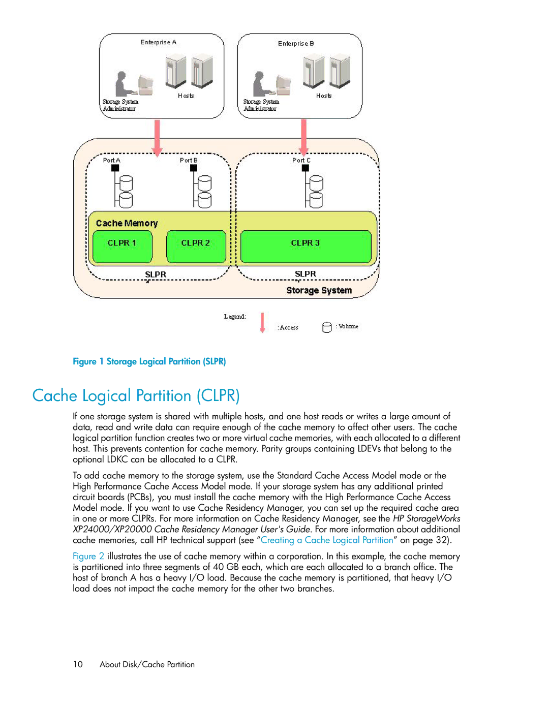
Figure 1 Storage Logical Partition (SLPR)
.
Cache Logical Partition (CLPR)
If one storage system is shared with multiple hosts, and one host reads or writes a large amount of data, read and write data can require enough of the cache memory to affect other users. The cache logical partition function creates two or more virtual cache memories, with each allocated to a different host. This prevents contention for cache memory. Parity groups containing LDEVs that belong to the optional LDKC can be allocated to a CLPR.
To add cache memory to the storage system, use the Standard Cache Access Model mode or the High Performance Cache Access Model mode. If your storage system has any additional printed circuit boards (PCBs), you must install the cache memory with the High Performance Cache Access Model mode. If you want to use Cache Residency Manager, you can set up the required cache area in one or more CLPRs. For more information on Cache Residency Manager, see the HP StorageWorks XP24000/XP20000 Cache Residency Manager User's Guide. For more information about additional cache memories, call HP technical support (see “Creating a Cache Logical Partition” on page 32).
Figure 2 illustrates the use of cache memory within a corporation. In this example, the cache memory is partitioned into three segments of 40 GB each, which are each allocated to a branch office. The host of branch A has a heavy I/O load. Because the cache memory is partitioned, that heavy I/O load does not impact the cache memory for the other two branches.
10 About Disk/Cache Partition