INSTALLATION
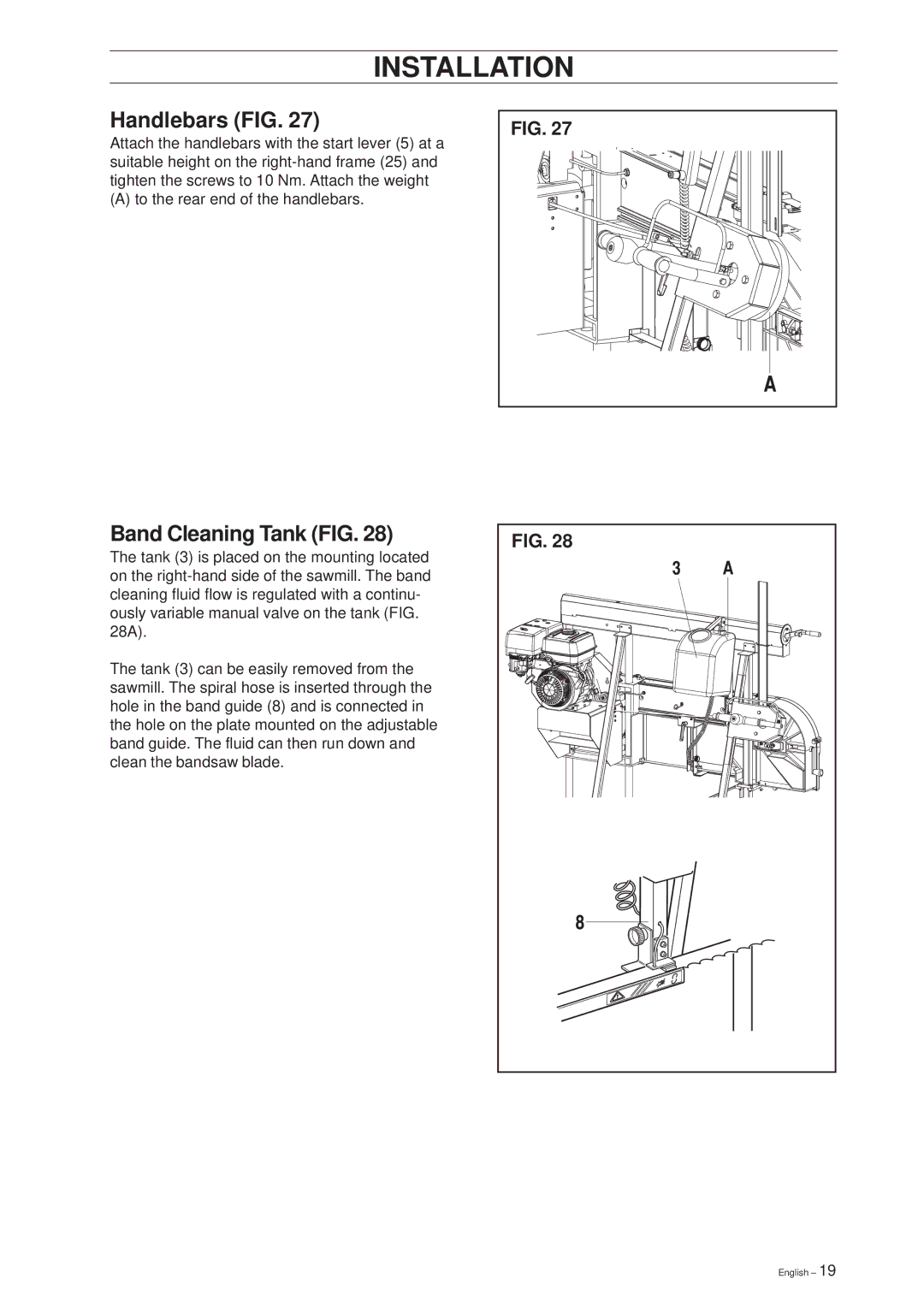
Handlebars (FIG. 27)
Attach the handlebars with the start lever (5) at a suitable height on the
(A) to the rear end of the handlebars.
Band Cleaning Tank (FIG. 28)
The tank (3) is placed on the mounting located on the
The tank (3) can be easily removed from the sawmill. The spiral hose is inserted through the hole in the band guide (8) and is connected in the hole on the plate mounted on the adjustable band guide. The fluid can then run down and clean the bandsaw blade.
FIG. 27
FIG. 28
English – 19
