BDM-610000049 specifications
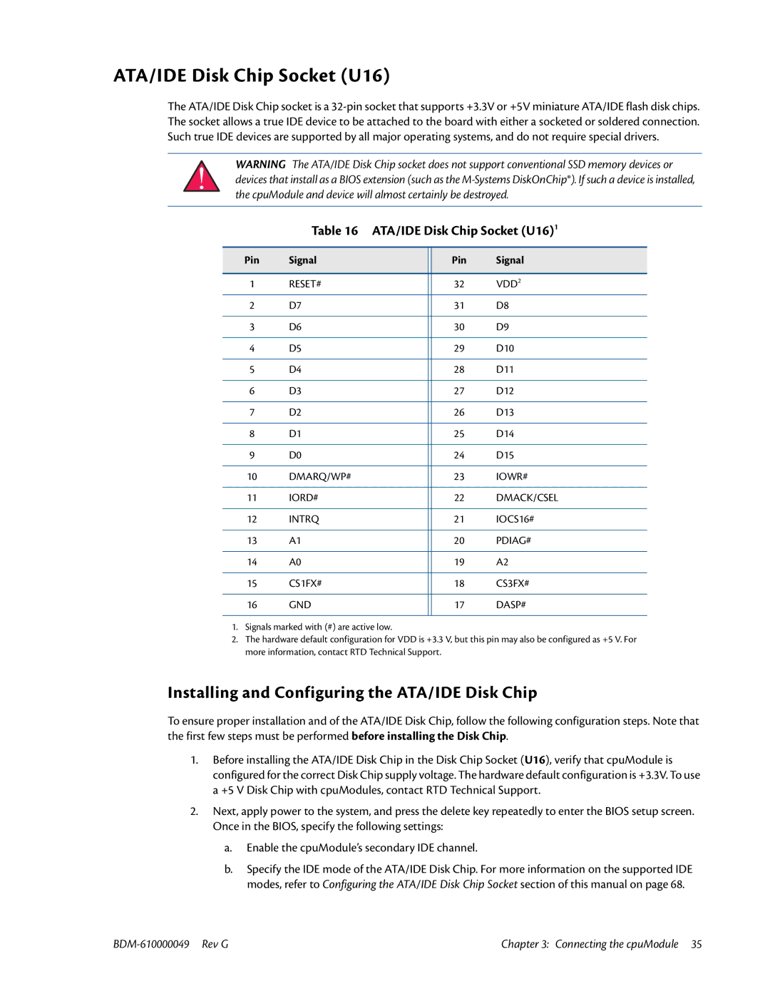
The IBM BDM-610000049 is a powerful and versatile device designed for advanced data processing and analytics. This model is engineered to handle large volumes of data while ensuring high-speed performance and reliability. One of the main features of the BDM-610000049 is its robust processing capabilities, enabled by a state-of-the-art multi-core CPU architecture. This allows it to perform complex calculations and data manipulations efficiently, making it ideal for big data applications.In terms of storage, the BDM-610000049 comes equipped with high-capacity SSD drives, which not only accelerate data access speeds but also enhance the overall system responsiveness. This feature is particularly beneficial for organizations that require rapid retrieval of stored information. The device also supports a variety of storage configurations, allowing users to tailor the system according to their specific needs, balancing between performance and capacity.
Networking technologies integrated into the BDM-610000049 are designed to facilitate seamless connectivity, ensuring quick and secure data transfers. Its advanced networking capabilities include support for multiple protocols, which streamline communication between different parts of the system and external devices. This is crucial for environments that rely on real-time data processing, such as financial services, healthcare, and logistics.
The IBM BDM-610000049 is also notable for its security features, which help protect sensitive data from unauthorized access and cyber threats. It incorporates state-of-the-art encryption protocols and secure access controls, providing an additional layer of safety for businesses handling critical information.
Moreover, the scalability of the BDM-610000049 is a key characteristic that sets it apart from competitors. Organizations can easily upgrade or expand their systems to accommodate growing data requirements without significant downtime or disruption. This flexibility is indispensable for businesses in today’s fast-paced digital landscape.
In summary, the IBM BDM-610000049 is a cutting-edge device that combines powerful processing, advanced storage technologies, robust networking capabilities, and enhanced security features. Its scalability ensures that it can grow with the demands of modern enterprises, making it a worthwhile investment for companies looking to harness the full power of their data. With the BDM-610000049, businesses can confidently pursue data-driven strategies, knowing they have a reliable and sophisticated technology solution at their disposal.

