N | May 1999 |
Rev 1.0.0 |
CLC-CAPT-PCASM
Data Capture Board User’s Guide
Section I. Introduction | Table of Contents |
The CLC3790093 Data Capture Board enables simple evaluation | I. Introduction |
of National Semiconductor’s High Speed Analog to Digital Con- | II. Capturing Data from ADC |
verters (ADCs) and the Diversity Receiver Chip Set (DRCS). The | Evaluation Boards |
Data Capture Board interfaces the outputs of these devices to the | III. Capturing Data from the DRCS |
standard serial port available on the back of most Personal | Evaluation Boards |
Computers (PCs). We have provided PC software to control the | IV. Data Analysis using Matlab |
data capture function and Matlab® scripts for data analysis. | Script Files |
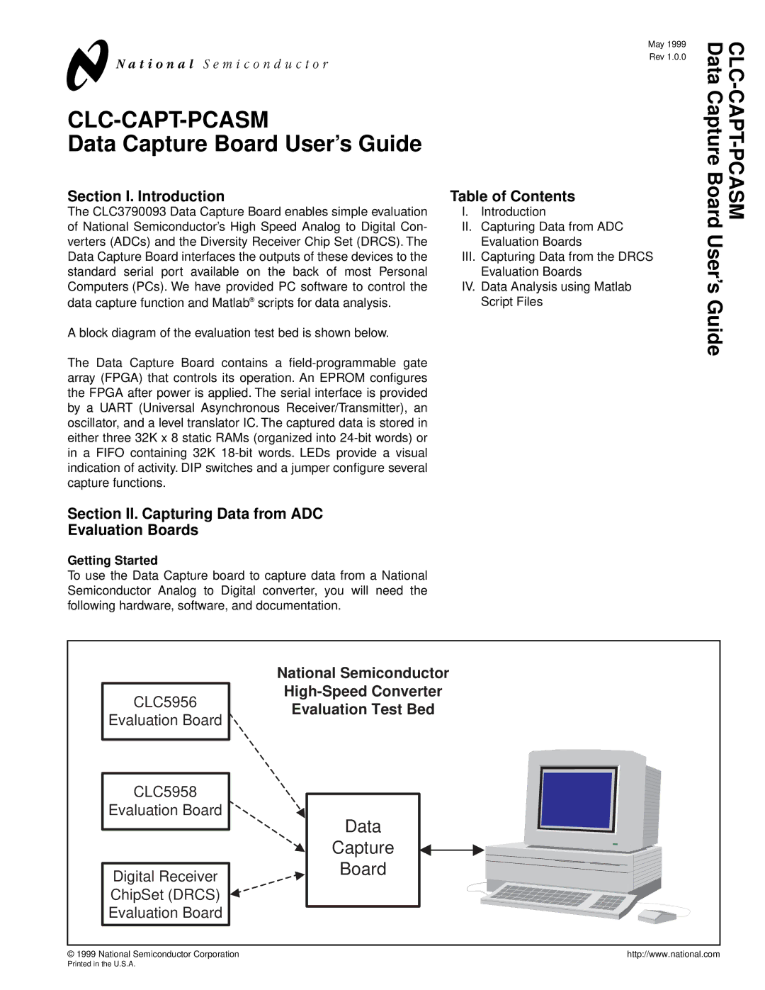
A block diagram of the evaluation test bed is shown below. |
|
The Data Capture Board contains a |
|
array (FPGA) that controls its operation. An EPROM configures |
|
the FPGA after power is applied. The serial interface is provided |
|
by a UART (Universal Asynchronous Receiver/Transmitter), an |
|
oscillator, and a level translator IC. The captured data is stored in |
|
either three 32K x 8 static RAMs (organized into |
|
in a FIFO containing 32K |
|
indication of activity. DIP switches and a jumper configure several |
|
capture functions. |
|
Data Capture Board |
|
User’s Guide |
|
Section II. Capturing Data from ADC
Evaluation Boards
Getting Started
To use the Data Capture board to capture data from a National Semiconductor Analog to Digital converter, you will need the following hardware, software, and documentation.
| National Semiconductor | |
CLC5956 | ||
Evaluation Test Bed | ||
Evaluation Board | ||
| ||
CLC5958 |
| |
Evaluation Board | Data | |
| ||
| Capture | |
Digital Receiver | Board | |
| ||
ChipSet (DRCS) |
| |
Evaluation Board |
| |
© 1999 National Semiconductor Corporation | http://www.national.com |
Printed in the U.S.A.