In this example, we have captured data from a
For more information about this analysis technique, please refer to Section IV of this document, the com- ments in the DNL_INL script file, or the IEEE Standard for Digitizing Waveform Recorders (IEEE Std
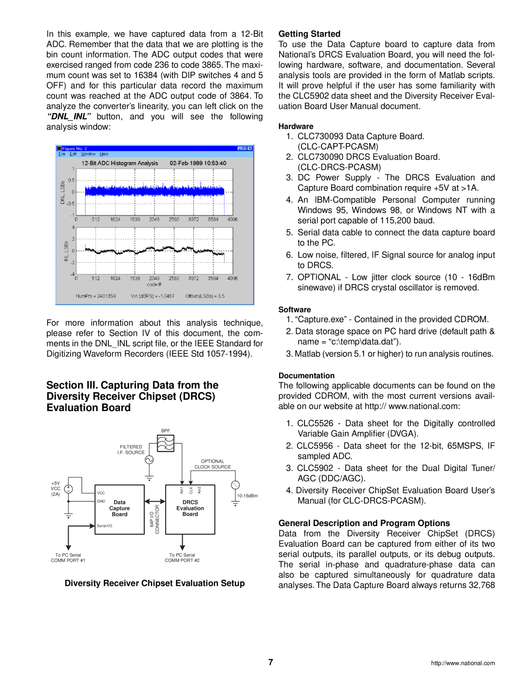
Section III. Capturing Data from the Diversity Receiver Chipset (DRCS) Evaluation Board
|
|
|
|
| BPF |
|
|
|
| FILTERED |
|
|
|
|
|
|
| I.F. SOURCE |
|
|
|
|
|
|
|
|
|
|
|
| OPTIONAL |
|
|
|
|
|
|
| CLOCK SOURCE |
+5V |
|
|
|
| Ain1 | CLK | Ain2 |
VCC | VCC |
|
|
| |||
|
|
|
|
|
| ||
(2A) |
|
|
|
|
| ||
|
|
|
|
|
|
| |
| GND | Data | I/O64P | CONNECTOR | DRCS | ||
|
| Capture | Evaluation | ||||
|
| Board |
|
| Board | ||
| Serial I/O |
|
|
|
|
| |
To PC Serial | To PC Serial |
COMM PORT #1 | COMM PORT #2 |
Diversity Receiver Chipset Evaluation Setup
7
Getting Started
To use the Data Capture board to capture data from National’s DRCS Evaluation Board, you will need the fol- lowing hardware, software, and documentation. Several analysis tools are provided in the form of Matlab scripts. It will prove helpful if the user has some familiarity with the CLC5902 data sheet and the Diversity Receiver Eval- uation Board User Manual document.
Hardware
1.CLC730093 Data Capture Board.
2.CLC730090 DRCS Evaluation Board.
3.DC Power Supply - The DRCS Evaluation and Capture Board combination require +5V at >1A.
4.An
5.Serial data cable to connect the data capture board to the PC.
6.Low noise, filtered, IF Signal source for analog input to DRCS.
7.OPTIONAL - Low jitter clock source (10 - 16dBm sinewave) if DRCS crystal oscillator is removed.
Software
1.“Capture.exe” - Contained in the provided CDROM.
2.Data storage space on PC hard drive (default path & name = “c:\temp\data.dat”).
3.Matlab (version 5.1 or higher) to run analysis routines.
Documentation
The following applicable documents can be found on the provided CDROM, with the most current versions avail- able on our website at http:// www.national.com:
1.CLC5526 - Data sheet for the Digitally controlled Variable Gain Amplifier (DVGA).
2.CLC5956 - Data sheet for the
3.CLC5902 - Data sheet for the Dual Digital Tuner/ AGC (DDC/AGC).
4.Diversity Receiver ChipSet Evaluation Board User’s Manual (for
General Description and Program Options
Data from the Diversity Receiver ChipSet (DRCS) Evaluation Board can be captured from either of its two serial outputs, its parallel outputs, or its debug outputs. The serial
http://www.national.com