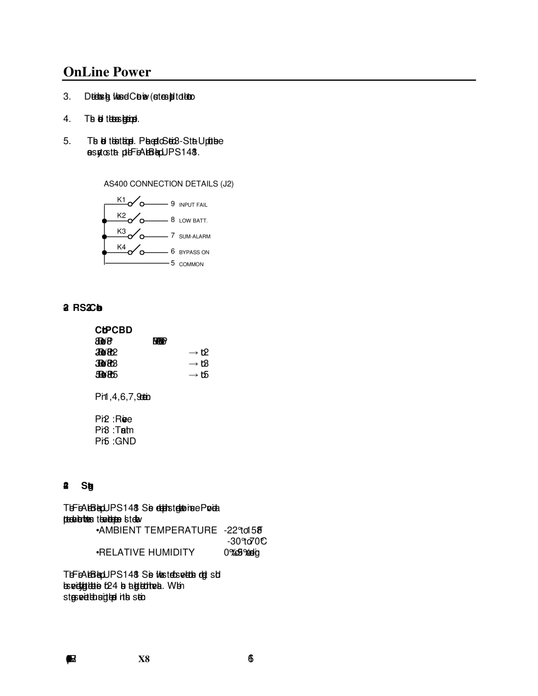
UPS1481 UNIT specifications
The IBM UPS1481 is a robust uninterruptible power supply (UPS) designed to ensure the seamless operation of critical equipment in various environments, including data centers, telecommunications, and enterprise applications. This model is particularly noted for its reliability, efficiency, and advanced features, catering to the demands of modern IT infrastructures.One of the main features of the UPS1481 is its high-capacity output, which can handle significant power loads. With an impressive power rating, the unit is equipped to support various devices, from servers to networking equipment, guaranteeing that essential operations remain uninterrupted during power outages or fluctuations. This capability is crucial for maintaining business continuity and minimizing potential downtime.
In terms of technology, the IBM UPS1481 integrates advanced power management systems that provide real-time monitoring and control. This functionality allows users to track power consumption, battery status, and overall system health through an intuitive interface. Additionally, the UPS includes features such as an automatic voltage regulator (AVR), which helps stabilize voltage levels, protecting connected equipment from surges, spikes, and drops that can cause damage or data loss.
The UPS1481 also comes with a modular design, allowing for scalability. Users can expand the capacity of the UPS to meet growing power demands without needing to replace the entire unit. This flexibility is beneficial for organizations undergoing rapid growth or technological upgrades.
Another important characteristic of the IBM UPS1481 is its energy efficiency. Designed to comply with various energy standards, the unit operates with minimal power loss, thereby reducing operational costs and contributing to a greener environment. By optimizing energy usage, organizations can enhance their sustainability initiatives while ensuring reliable power protection.
Furthermore, the UPS1481 offers a robust battery system that supports extended runtime options. Users can configure the UPS with additional battery packs to ensure that critical systems remain operational for extended periods during extensive outages.
In summary, the IBM UPS1481 UNIT stands out for its high capacity, advanced power management features, modular design, and energy efficiency. It is an ideal solution for businesses looking to safeguard their critical equipment and maintain operational integrity in the face of power disruptions.

