SECTION 4 CIRCUIT DESCRIPTION
4-1 RECEIVER CIRCUITS
4-1-1 RF FILTER CIRCUIT (PLL AND MAIN UNITS)
Received signals from the antenna connector are applied to the transmit/receive switching and protection relay (PLL unit; RL7301) which is controlled by the CPU via the “TRXS” line. The signals pass through the 30 MHz
The signals pass through the 1.6 MHz cut off
4-1-2 1ST MIXER AND IF CIRCUITS (MAIN UNIT)
The 1st mixer circuit converts the received signals into a fixed frequency, 64.445 kHz 1st IF signal using PLL output frequency. By changing the PLL frequency, only the desired frequency is picked up at the 64.445 kHz bandpass filter (FI201) at the next stage.
The IF amplifier (Q203) and resonator circuits are designed between the filter pair. The PLL output signal (1LO) enters the MAIN unit via the J601 and is amplified at the 1st LO amplifier (Q601). The amplified signal is passed through the
100MHz
4-1-3 2ND MIXER AND IF CIRCUITS (MAIN UNIT)
The filtered signals are applied to the
Frequency (MHz) | LPF ctrl signal | BPF ctrl signal | |
L1M | B0 | ||
B1 | |||
| |||
L2M | |||
| |||
B2 | |||
| |||
L4M | |||
| |||
B3 | |||
| |||
L6M | |||
| |||
B4 | |||
| |||
| |||
|
| ||
L12M | B5 | ||
| B6 | ||
| |||
|
| ||
L22M | B7 | ||
| B8 | ||
|
|
|
signals pass through the
The 1st IF signal from the bandpass filter (FI201) is convert- ed again into a 455 kHz 2nd IF signal at the 2nd mixer cir- cuit (D303, L303, L304). The 2nd LO signal (2LO) from the PLL unit enters the MAIN unit via the J301 to be applied to the 2nd mixer circuit.
4-1-4 3RD MIXER AND IF CIRCUITS (MAIN UNIT)
The 2nd IF signal passes through the
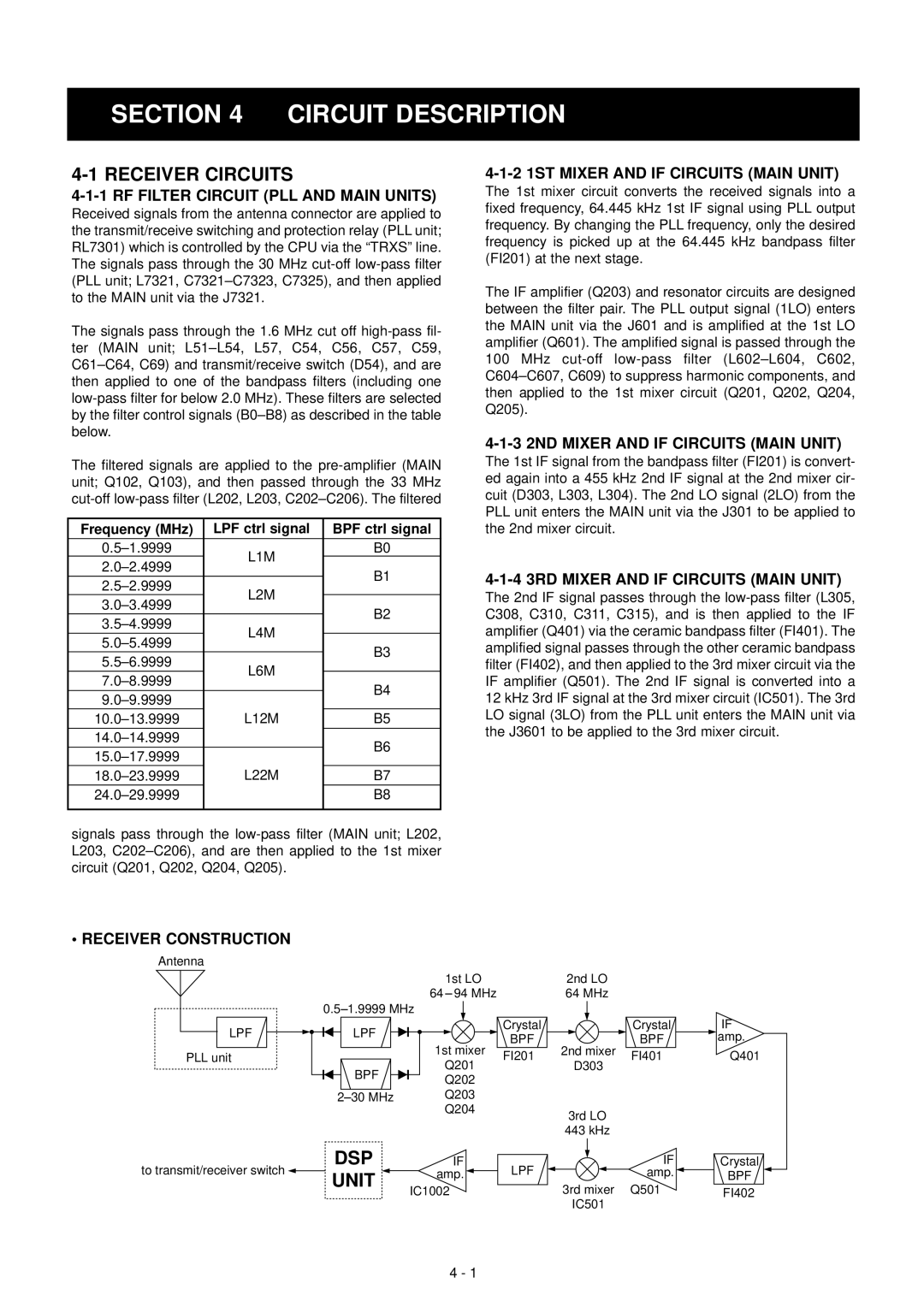
• RECEIVER CONSTRUCTION
Antenna
|
|
|
|
|
|
|
|
|
| 1st LO |
| 2nd LO |
|
| ||||||
| 64 |
|
| 94 MHz |
| 64 MHz |
|
| ||||||||||||
|
|
|
|
|
| |||||||||||||||
|
|
|
| 0.5 1.9999 MHz |
|
|
|
|
|
|
|
|
|
|
| |||||
LPF |
|
|
|
|
| LPF |
|
|
|
|
|
|
|
|
| Crystal |
|
| Crystal | IF |
|
|
|
|
|
|
| 1st mixer | BPF | 2nd mixer | BPF | amp. | |||||||||
PLL unit |
|
|
|
|
|
|
|
| FI201 | FI401 | Q401 | |||||||||
|
|
|
|
|
|
|
|
| Q201 | D303 | ||||||||||
|
|
|
|
|
| BPF |
|
|
|
|
| |||||||||
|
|
|
|
|
|
|
|
|
| Q202 |
|
|
|
|
| |||||
|
|
|
|
| 2 30 MHz | Q203 |
|
|
|
|
| |||||||||
|
|
|
|
|
|
|
|
|
| Q204 |
| 3rd LO |
|
| ||||||
|
|
|
|
|
|
|
|
|
|
|
|
|
|
|
|
|
|
| ||
|
|
|
|
|
|
|
|
|
|
|
|
|
|
|
|
| 443 kHz |
|
| |
to transmit/receiver switch ![]()
DSP
UNIT
IF | LPF | IF | Crystal |
amp. | amp. | BPF | |
IC1002 |
| 3rd mixer Q501 | FI402 |
|
| IC501 |
|
4 - 1