SSI
|
|
|
|
| ERP2U Power Supply Design Guide, V1.0 | ||
|
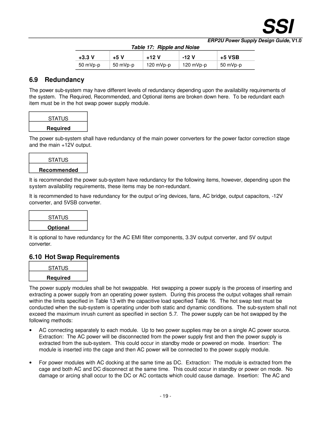
| Table 17: Ripple and Noise |
|
|
| ||
| +3.3 V | +5 V | +12 V |
| +5 VSB |
| |
| 50 | 50 | 120 | 120 |
| 50 | |
|
|
|
|
|
|
|
|
6.9Redundancy
The power
STATUS
Required
The power
STATUS
Recommended
It is recommended the power
It is recommended to have redundancy for the output or’ing devices, fans, AC bridge, output capacitors,
STATUS
Optional
It is optional to have redundancy for the AC EMI filter components, 3.3V output converter, and 5V output converter.
6.10 Hot Swap Requirements
STATUS
Required
The power supply modules shall be hot swappable. Hot swapping a power supply is the process of inserting and extracting a power supply from an operating power system. During this process the output voltages shall remain within the limits specified in Table 13 with the capacitive load specified Table 16. The hot swap test must be conducted when the
∙AC connecting separately to each module. Up to two power supplies may be on a single AC power source. Extraction: The AC power will be disconnected from the power supply first and then the power supply is extracted from the
∙For power modules with AC docking at the same time as DC. Extraction: The module is extracted from the cage and both AC and DC disconnect at the same time. This could occur in standby or power on mode. No damage or arcing shall occur to the DC or AC contacts which could cause damage. Insertion: The AC and
-19 -