SSI
ERP2U Power Supply Design Guide, V1.0
8Control and Indicator Functions
The following sections define the input and output signals from the power supply.
Signals that can be defined as low true use the following convention:
signal# = low true
8.1PSON#
STATUS
Required
The PSON# signal is required to remotely turn on/off the power supply. PSON# is an active low signal that turns on the +3.3 V, +5 V, +12 V, and
| Table 23: PSON# Signal Characteristic |
| |
Signal Type |
| Accepts an open collector/drain input from the system. | |
| |||
|
| ||
|
|
|
|
PSON# = Low |
| ON |
|
PSON# = Open or High | OFF |
| |
|
| MIN | MAX |
Logic level low (power supply ON) | 0 V | 1.0 V | |
|
| ||
Logic level high (power supply OFF) | 2.0 V | 5.25 V | |
|
| ||
Source current, Vpson = low |
| 4 mA | |
|
| ||
Power up delay: | Tpson_on_delay | 5 ms | 400 ms |
|
| ||
PWOK delay: | T pson_pwok |
| 50 ms |
|
| ||
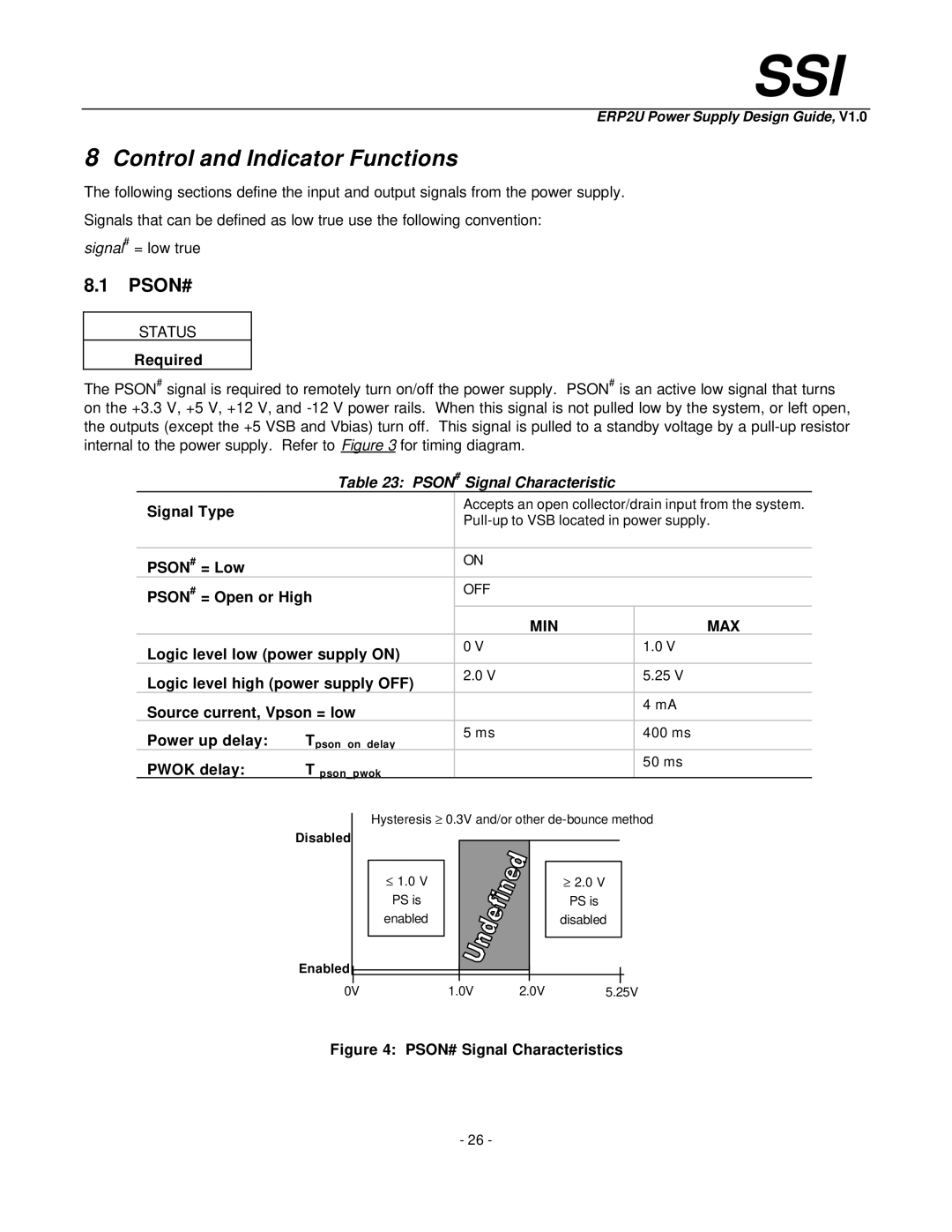
Disabled
Enabled
Hysteresis ³ 0.3V and/or other
£ 1.0 V | ³ 2.0 V |
PS is | PS is |
enabled | disabled |
0V | 1.0V | 2.0V | 5.25V |
Figure 4: PSON# Signal Characteristics
- 26 -