SSI
ERP2U Power Supply Design Guide, V1.0
6.4.1Standby Outputs
STATUS
Required
The 5 VSB output shall be present when an AC input greater than the power supply turn on voltage is applied.
6.5Voltage Regulation
STATUS
Required
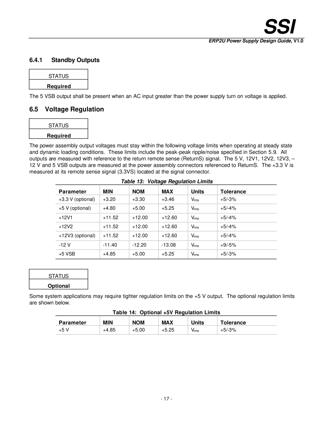
The power assembly output voltages must stay within the following voltage limits when operating at steady state and dynamic loading conditions. These limits include the
Table 13: Voltage Regulation Limits
| Parameter | MIN | NOM | MAX | Units | Tolerance | |
| +3.3 V (optional) | +3.20 | +3.30 | +3.46 | Vrms | ||
|
|
|
|
|
|
|
|
| +5 V (optional) | +4.80 | +5.00 | +5.25 | Vrms | ||
|
|
|
|
|
|
|
|
| +12V1 | +11.52 | +12.00 | +12.60 | Vrms | ||
|
|
|
|
|
|
|
|
| +12V2 | +11.52 | +12.00 | +12.60 | Vrms | ||
|
|
|
|
|
|
|
|
| +12V3 (optional) | +11.52 | +12.00 | +12.60 | Vrms | ||
|
|
|
|
|
|
|
|
| Vrms | ||||||
|
|
|
|
|
|
|
|
| +5 VSB | +4.85 | +5.00 | +5.25 | Vrms | ||
|
|
|
|
|
|
|
|
|
|
|
|
|
|
| |
STATUS |
|
|
|
|
|
| |
Optional |
|
|
|
|
|
| |
Some system applications may require tighter regulation limits on the +5 V output. The optional regulation limits are shown below.
| Table 14: Optional +5V | Regulation Limits |
| ||||
Parameter | MIN | NOM | MAX |
| Units |
| Tolerance |
+5 V | +4.85 | +5.00 | +5.25 |
| Vrms |
| |
|
|
|
|
|
|
|
|
- 17 -